
Hydrogen generator with reactant dilution scheme

a technology of reactant dilution and hydrogen generator, which is applied in the direction of gas generation devices, liquid-gas reaction of thin-film type, inorganic chemistry, etc., can solve the problems that the commercial implementation of hydrogen generators based on sodium borohydride has encountered some significant challenges

Inactive Publication Date: 2010-06-17
LYNNTECH
View PDF3 Cites 46 Cited by
  • Summary
  • Abstract
  • Description
  • Claims
  • Application Information

AI Technical Summary

Benefits of technology

The patent describes a hydrogen generator that can produce hydrogen gas by reacting a solution of hydrogen-containing material in a liquid medium. The generator has multiple fluidic pathways that allow the solution to flow through the generator and react with a catalyst to produce hydrogen gas. The generator can be flexible and enclosed in a pressurized chamber. The technical effects of this invention include a more efficient and flexible way to produce hydrogen gas.

Problems solved by technology

However, despite these advantages, the commercial implementation of hydrogen generators based on sodium borohydride has encountered some significant challenges.

Method used


Image

  • Hydrogen generator with reactant dilution scheme
  • Hydrogen generator with reactant dilution scheme
  • Hydrogen generator with reactant dilution scheme

Examples


first embodiment

B. First Embodiment

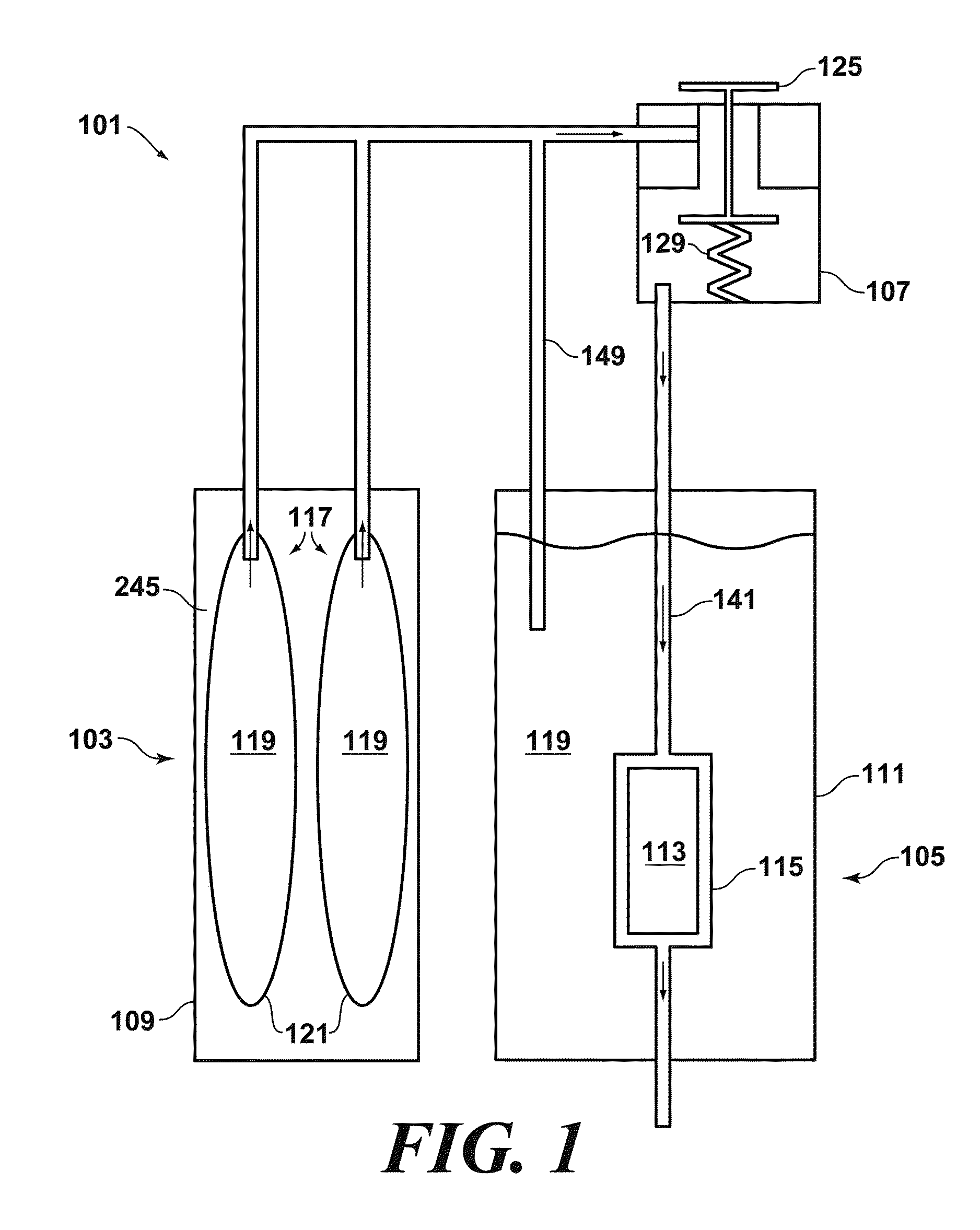
[0023]FIG. 1 depicts a first particular, non-limiting embodiment of a hydrogen generator made in accordance with the teachings herein. The hydrogen generator 101 depicted therein comprises a first reservoir 103 which is in fluidic communication with a second reservoir 105 via a regulator 107. Preferably, the first 103 and second 105 reservoirs are equipped, respectively, with first 109 and second 111 rigid housings, and the pressure inside of sub-reservoirs 117 and second housing 111 is the same or is similar.

[0024]The second reservoir 105 contains a hydrogen-containing material 113. Preferably, the hydrogen-containing material 113 is disposed within a casing 115. The casing 115 preferably comprises an elastomeric material which can conform to the shape of the hydrogen-containing material 113 such that, as the hydrogen-containing material is consumed and shrinks in volume, the casing shrinks correspondingly. In the particular embodiment depicted, the hydrogen-cont...

second embodiment

C. Variation on Second Embodiment

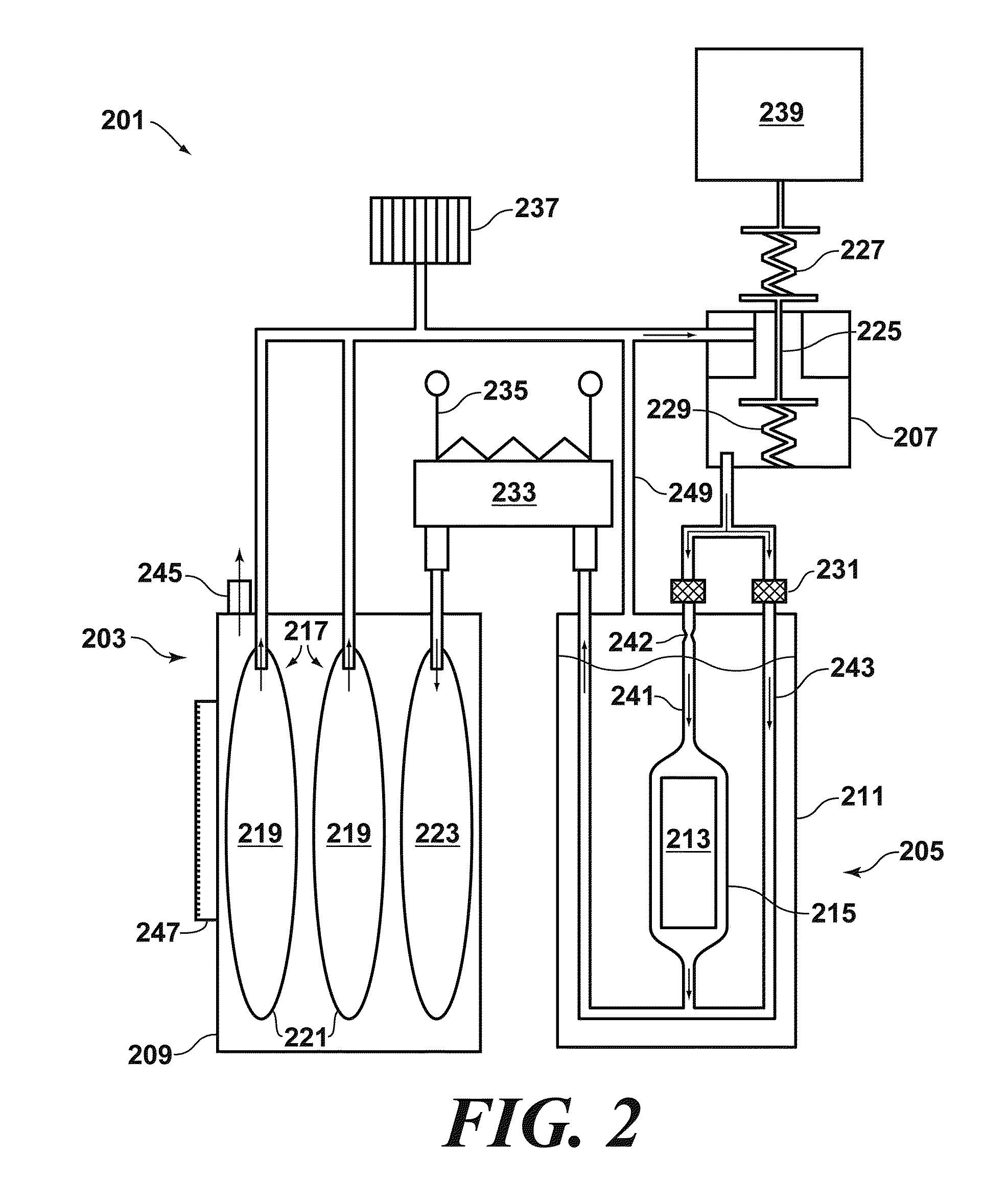
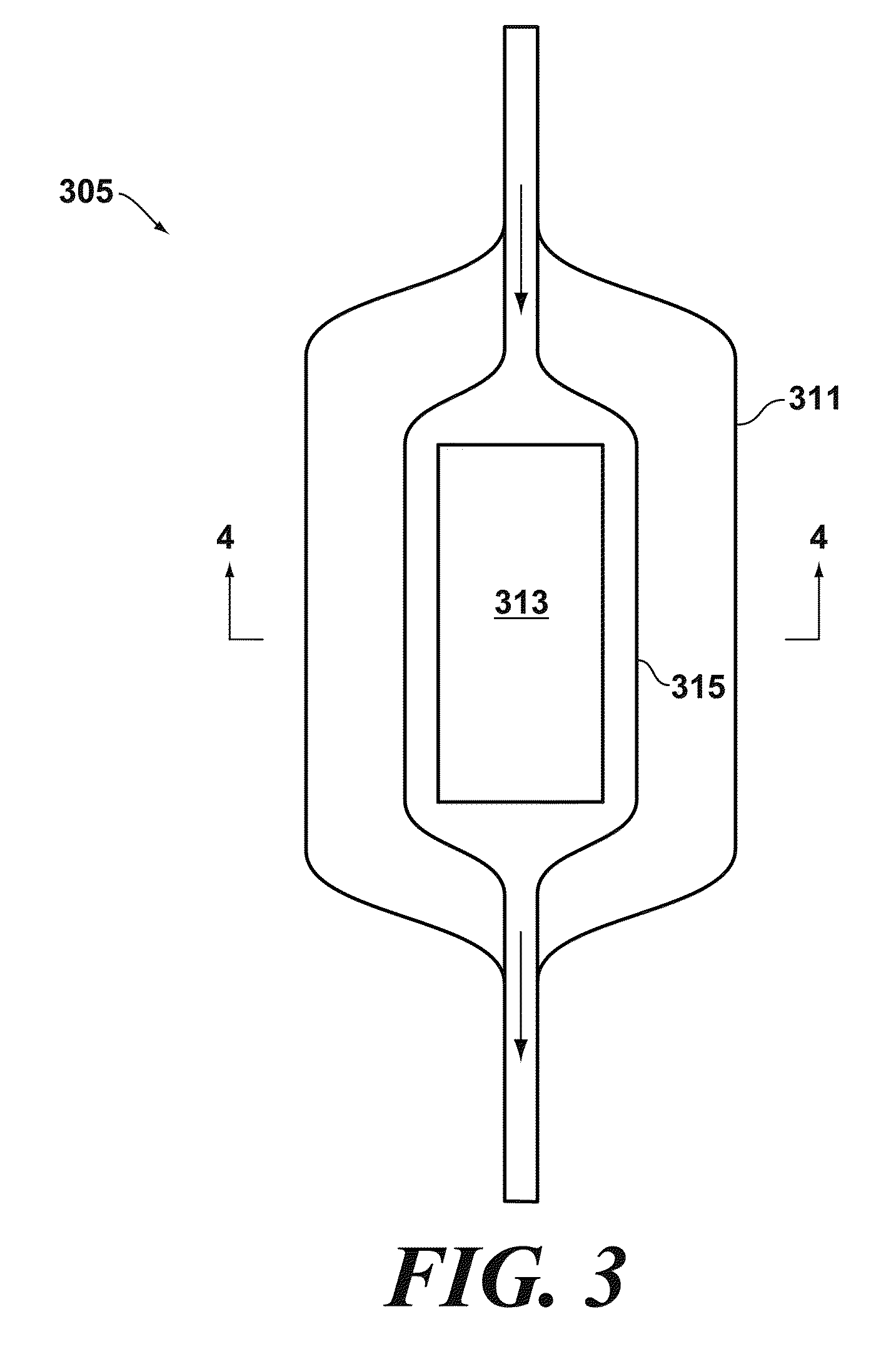
[0040]FIGS. 3-4 depict a further possible variation of the second reservoir 205 of FIG. 2. Unlike the embodiment of FIG. 2 in which the second reservoir 205 is preferably equipped with a rigid housing 211, the second reservoir 305 depicted in FIGS. 3-4 is equipped with an elastomeric housing 311. Such an embodiment is advantageous in that the elastomeric housing 311 applies essentially uniform pressure to the casing 315, irrespective of its geometry or volume, and without having to be pressurized. Hence, the pressure applied by the elastomeric housing 311 remains essentially uniform even as the volume of the casing 315 decreases due to consumption of the hydrogen-containing material disposed therein. The remaining elements in this embodiment are similar to their like numbered counterparts in FIG. 2.

D. Elastomeric Materials

[0041]Various flexible and / or elastomeric materials may be utilized in the construction of the housing 311, casing 315, the elasto...


PUM

PropertyMeasurementUnit
elastomericaaaaaaaaaa
pressureaaaaaaaaaa
concentrationaaaaaaaaaa

Abstract

A hydrogen generator (201) is provided which comprises (a) a chamber (205) having a hydrogen-containing material (213) disposed therein; (b) a first fluidic pathway (241) containing said chamber, said first fluidic pathway including an upstream portion which is upstream of said chamber, and a downstream portion which is downstream from said chamber; (c) a second fluidic pathway (243) which does not include said chamber, and which is adjoined to said first fluidic pathway downstream from said chamber; and (d) a reservoir (203) containing a liquid medium in which said hydrogen-containing material is soluble, said reservoir being in fluidic communication with at least one of said first and second fluidic pathways.

Description

CROSS REFERENCE TO RELATED APPLICATION[0001]This application claims the benefit of priority from U.S. Application No. 61 / 117,023, filed Nov. 21, 2009, having the same title, and having the same inventors, and which is incorporated herein by reference in its entirety.FIELD OF THE DISCLOSURE[0002]The present disclosure relates generally to hydrogen generators, and more particularly to hydrogen generators equipped with a reactant dilution scheme.BACKGROUND OF THE DISCLOSURE[0003]Hydrogen generators are devices that generate hydrogen gas for use in fuel cells, combustion engines, and other devices, often through the evolution of hydrogen gas from chemical hydrides, borohydrides, boranes, or other hydrogen-containing materials. Sodium borohydride (NaBH4) has emerged as a particularly desirable chemical hydride for use in such devices, due to the molar equivalents of hydrogen it generates (see EQUATION 1 below), the relatively low mass of NaBH4 as compared to some competing materials, and...

Claims


Application Information

Patent Timeline
Patent Type & Authority Applications(United States)
IPC IPC(8): B01J15/00B01J19/00C01B3/02
CPCB01J7/02Y02E60/362C01B5/00C01B3/065F17C11/005Y02E60/32Y02E60/36
Inventor WITHERS-KIRBY, SANDRASTEVENS, JADYNAGARAJ, MAHAVIR
Owner LYNNTECH
Learn More