
Sampling device and method in wireless communication system

a wireless communication system and sampling device technology, applied in the direction of transmission monitoring, instruments, using reradiation, etc., can solve the problems of affecting the accuracy the inability to detect the non-continuous pulse signal in a time domain, and the general difference in the timing obtained in the preamble period from the reception timing of the sampling device, etc., to achieve low complexity, low power consumption, and low cost

Inactive Publication Date: 2010-06-17
ELECTRONICS & TELECOMM RES INST
View PDF6 Cites 1 Cited by
  • Summary
  • Abstract
  • Description
  • Claims
  • Application Information

AI Technical Summary

Benefits of technology

[0025]The exemplary embodiment of the present invention is to provide a distance measuring unit that is capable of precisely extracting timing information while using a sampling device having low complexity for measuring a distance between asynchronous nodes.
[0032]Another embodiment of the present invention provides a sampling method in a wireless communication system that allows a receiver to sample signals, including: delaying the received signal in a block unit when the reception of the signal is detected; sampling on each delayed block; combining at least two sampled blocks; and tracking reception timing of the combined signal.
[0034]With the present invention, even though a low-speed sampling device is used, the same effect as with high-speed sampling can be obtained by inserting a unit adding a delay having a predetermined value in a reception process. In other words, since accurate timing information can be obtained using the sampling device having low complexity and low power consumption, an inexpensive and highly-integrated sampling device can be implemented.

Problems solved by technology

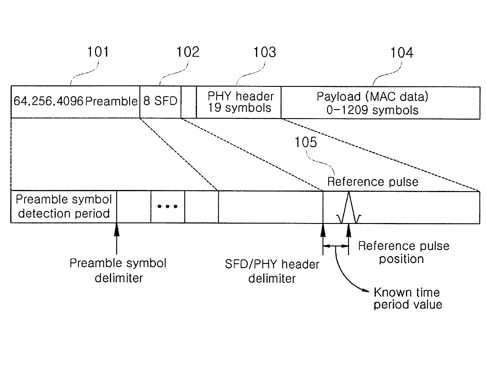
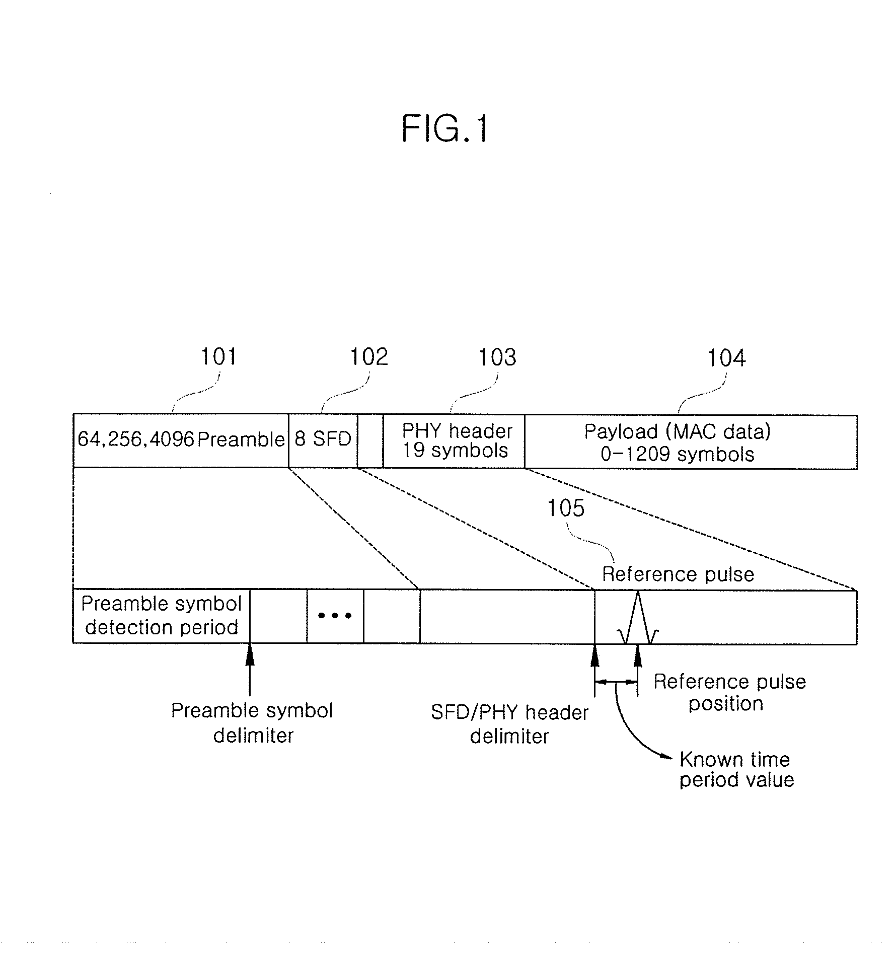
However, the timing obtained in a preamble period may be generally different from the reception timing of RMARKER due to clock mismatch between a transmission period and a reception period.
However, since the sampling device of 1 Gsps tracks timing with resolution of 1 nsec, an error of 1 nsec may occur, which appears as a distance error of 30cm in a distance measurer.
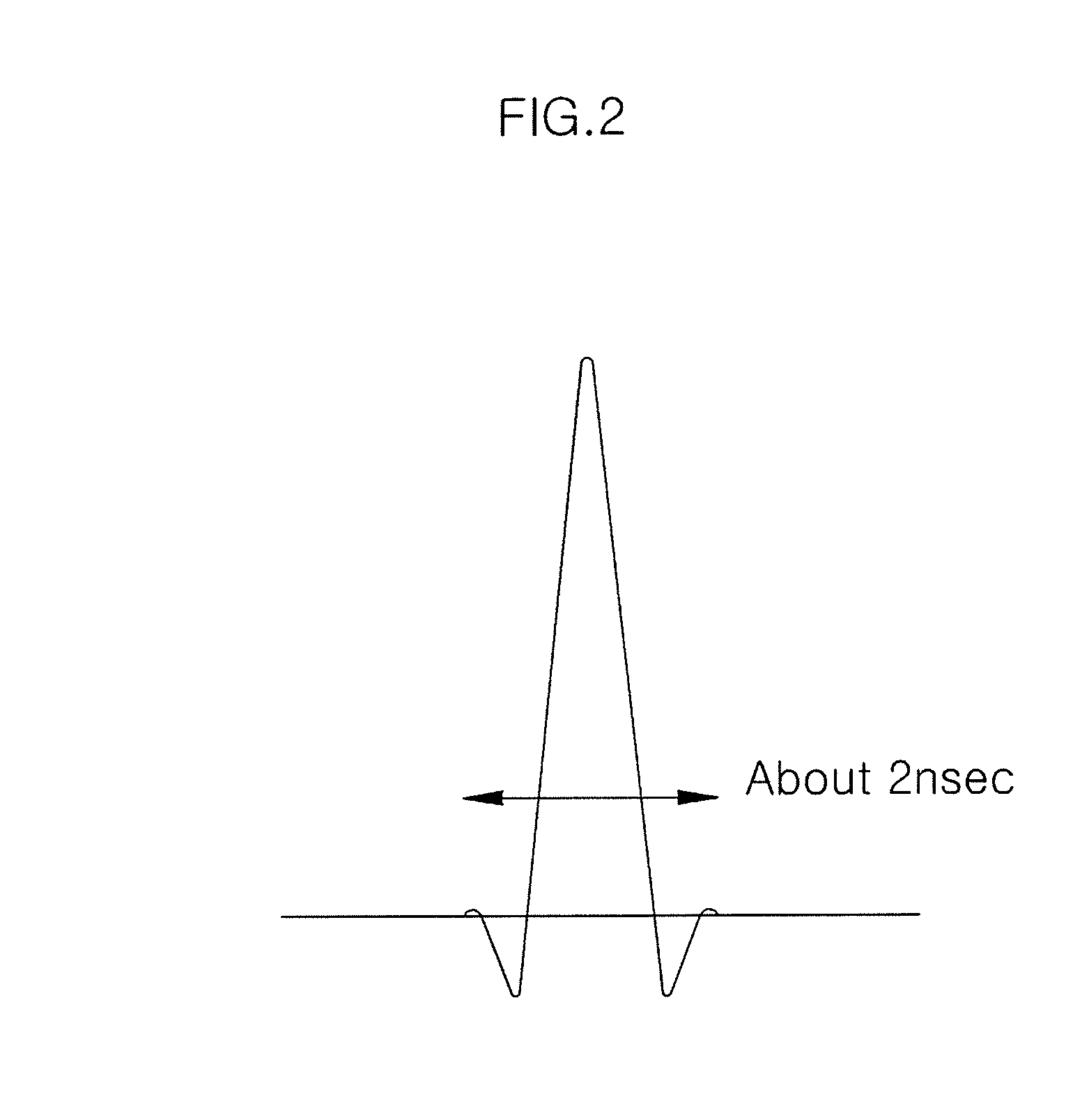
If the sampling is insufficient, it is possible to miss the non-continuous pulse signals in a time domain.
However, an analog-to-digital converter that is capable of performing the high-speed sampling is very expensive and has high power consumption, such that it is difficult to adopt it in the system.
Moreover, even though the sampling is performed at high speed, it is difficult to implement a precise timing tracker due to structural limitations in processing digital signals in the related art.

Method used


Image

  • Sampling device and method in wireless communication system
  • Sampling device and method in wireless communication system
  • Sampling device and method in wireless communication system

Examples


Embodiment Construction

[0044]In the following detailed description, only certain exemplary embodiments of the present invention have been shown and described, simply by way of illustration. As those skilled in the art would realize, the described embodiments may be modified in various different ways, all without departing from the spirit or scope of the present invention. Accordingly, the drawings and description are to be regarded as illustrative in nature and not restrictive. Like reference numerals designate like elements throughout the specification.

[0045]Throughout the specification, in addition, unless explicitly described to the contrary, the word “comprise” and variations such as “comprises” or “comprising” will be understood to imply the inclusion of stated elements but not the exclusion of any other elements. In addition, the terms “-er”, “-or”, and “module” described in the specification mean units for processing at least one function and operation and can be implemented by hardware components ...


PUM


Abstract

The exemplary embodiment of present invention provides a sampling device and method in a wireless communication system that is capable of precisely measuring a distance by combining data blocks passing through at least two delay paths and performing sampling thereon.To this end, the sampling device includes: a delayer that delays received signals in a block unit; a delay path selector that selects any one of a plurality of delay paths to control the delayer to apply the selected delay path to each block; a sampler that performs sampling for each block delayed by the delayer; a signal processor that combines at least two sampling blocks sampled by the sampler; and a timing tracker that tracks reception timing of the combined signal, wherein the delayer includes at least two selectable delay paths.

Description

CROSS-REFERENCE TO RELATED APPLICATION[0001]This application claims priority to and the benefit of Korean Patent Application Nos. 10-2008-0126112 and 10-2009-0027097 filed in the Korean Intellectual Property Office on Dec. 11, 2008 and Mar. 30, 2009, the entire contents of which are incorporated herein by reference.BACKGROUND OF THE INVENTION[0002](a) Field of the Invention[0003]The exemplary embodiment of the present invention relates to a sampling device and method in a wireless communication system.[0004](b) Description of the Related Art[0005]Recently, a wireless technology of an impulse scheme is increasingly gaining attention as a promising technology such that it is being adopted as a physical layer technology of IEEE 802.15.4a that is an international standard of Wireless Personal Area Network (WPAN) for low speed position recognition, due to its low power consumption and unique distance estimation capability.[0006]IEEE 802.15.4a has adopted the two way ranging (TWR) techniq...

Claims


Application Information

Patent Timeline
Patent Type & Authority Applications(United States)
IPC IPC(8): H04B17/00
CPCG01S13/765H04L7/0041H04L7/042
Inventor OH, MI-KYUNGPARK, JOO HOOH, JUNG-YEOLKIL, MIN SUKIM, JAE YOUNG
Owner ELECTRONICS & TELECOMM RES INST
Learn More