Lock-up clutch control device

Inactive Publication Date: 2010-06-10
TOYOTA JIDOSHA KK
View PDF3 Cites 14 Cited by
  • Summary
  • Abstract
  • Description
  • Claims
  • Application Information

AI Technical Summary

Benefits of technology

[0034]In accordance with the present invention, it becomes possible to execute hydraulic pressure control of lock-up smooth off control more appropriately in a lock-up clutch control device executing deceleration lock-up control performing engagement control of the lock-up clutch and lock-up smooth off control upon deceleration of the vehicle.

Problems solved by technology

It should be noted that, although learning correction of a deceleration lock-up differential pressure (low-pressure engagement pressure) is desirable during deceleration lock-up control, the lock-up clutch needs to be reliably maintained in an engagement condition during deceleration lock-up control, and therefore, execution of feedback control of the deceleration lock-up differential pressure and performing learning correction is difficult.

Method used


Image

  • Lock-up clutch control device
  • Lock-up clutch control device
  • Lock-up clutch control device

Examples


Embodiment Construction

[0070]The following is a description of embodiments of the present invention, with reference to the drawings.

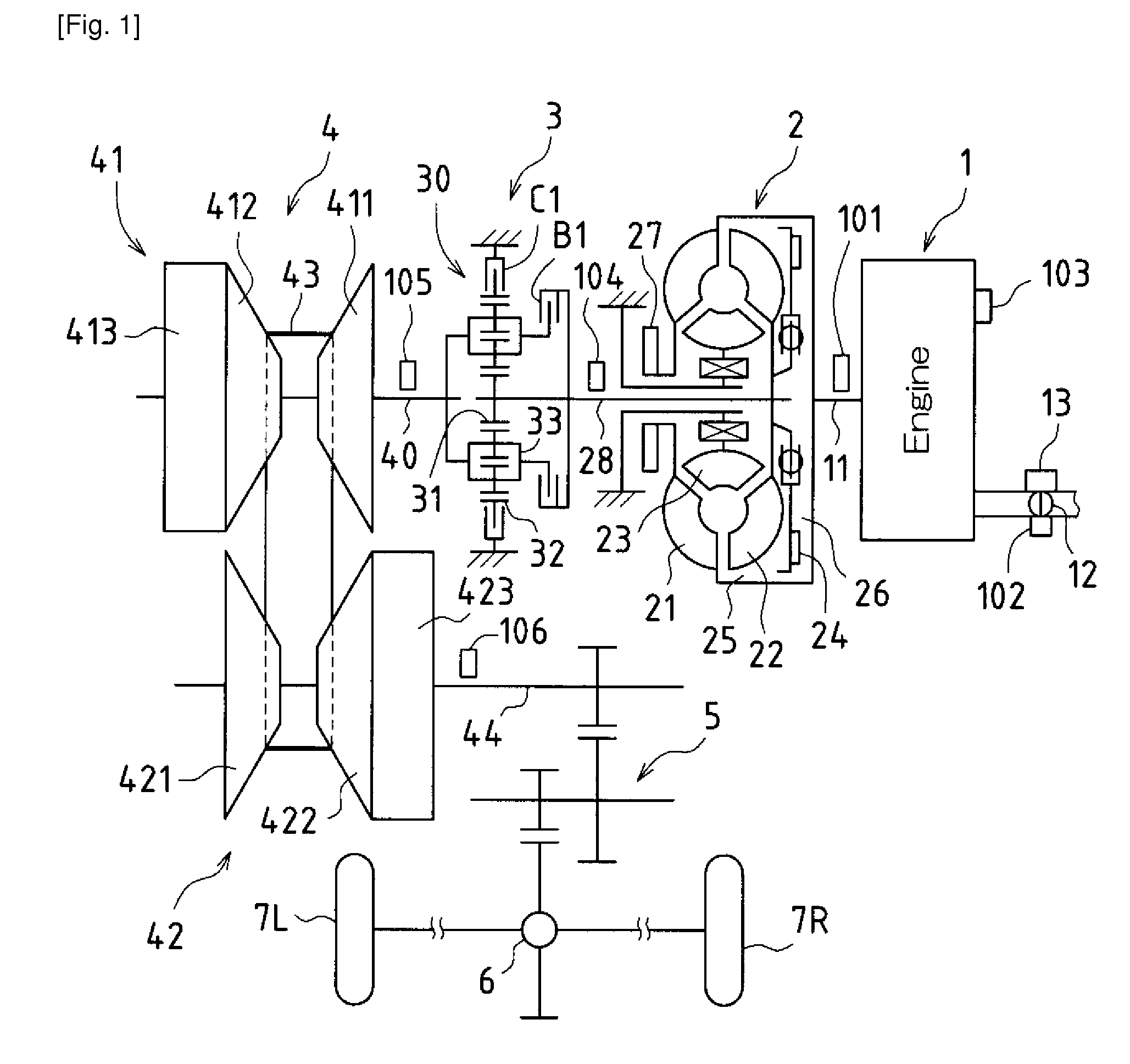
[0071]FIG. 1 is a schematic configuration diagram of a vehicle to which the present invention is applied.

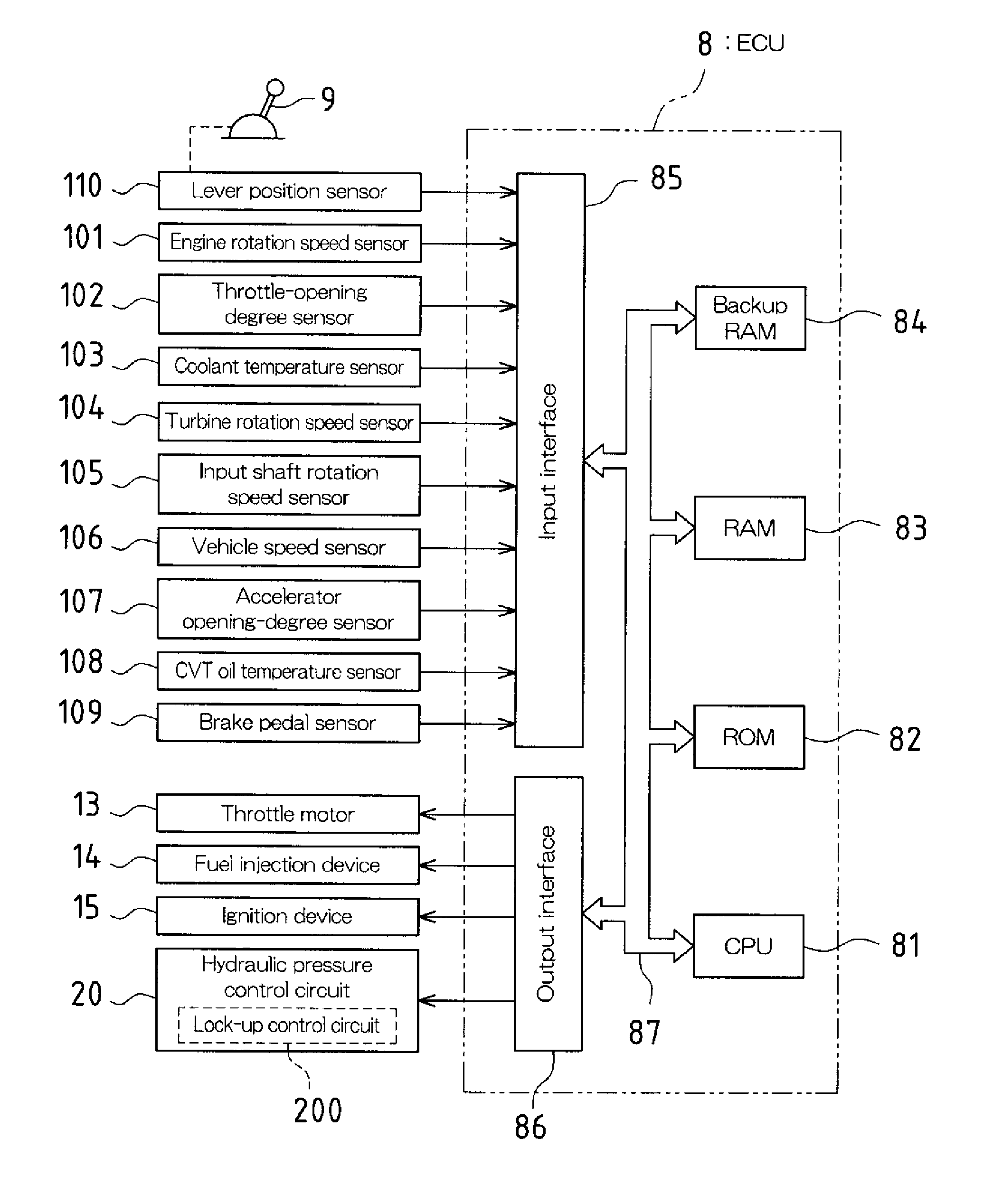
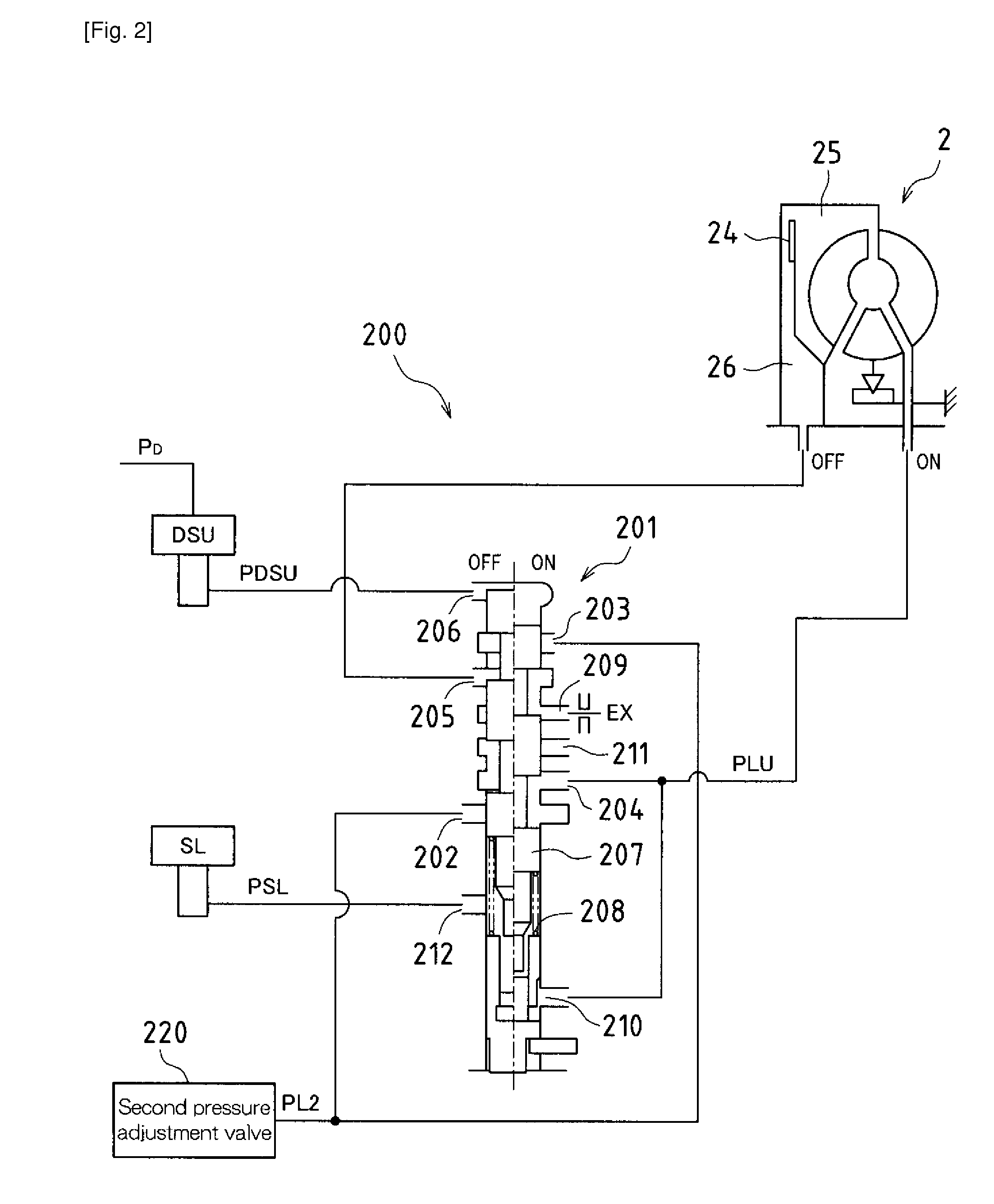
[0072]The vehicle of this example is an FF (front-engine, front-drive) type vehicle where an engine (internal combustion engine) 1 constituting a source of motive power for driving, a torque converter 2 as a hydraulic power transmission device, a forward-reverse switching device 3, a belt-type continuously variable transmission (CVT) 4, a deceleration gear device 5, a differential gear device 6, and an ECU (Electronic Control Unit) 8 (see FIG. 3) etc., are mounted, and a lock-up control device is realized, for example, by that ECU 8 and a lock-up control circuit 200 (hydraulic pressure control circuit 20) described hereinafter.

[0073]A crankshaft 11 constituting an output shaft of the engine 1 is connected to the torque converter 2, and an output of the engine 1 is transmit...


PUM


Abstract

When deceleration lock-up differential pressure learning control is entered and a difference between this deceleration lock-up differential pressure instruction value and a disengagement initial pressure of lock-up smooth off control becomes smaller than prior to deceleration lock-up differential pressure learning control, the disengagement initial pressure PS of lock-up smooth off control is corrected to a low side in accordance with a difference between that deceleration lock-up differential pressure instruction value and the disengagement initial pressure. Furthermore, by changing the sweep gradient of lock-up smooth off control to a small side, and in addition, correcting the disengagement initial pressure PS of lock-up smooth off control to a low side in consideration of disengagement delay of the lock-up clutch pursuant to that sweep gradient change, the actual disengagement time during lock-up smooth off control can be matched with a target disengagement time.

Description

TECHNICAL FIELD[0001]The present invention relates to a control device of a lock-up clutch directly connecting an input side and an output side of a hydraulic power transmission device disposed between a motive power source such as an engine (internal combustion engine), etc. and an automatic transmission mounted in a vehicle.BACKGROUND ART[0002]In a vehicle where an engine (internal combustion engine) is mounted, an automatic transmission automatically and optimally setting a gear ratio between the engine and a drive wheel is known as a transmission for suitably transmitting torque and rotation speed generated by the engine to the drive wheel in accordance with a driving condition of the vehicle.[0003]For example, a planetary gear type transmission setting a gear ratio (gear position) using a clutch, a brake, and a planetary gear device, and a belt-type continuously variable transmission (CVT) performing stepless adjustment of a gear ratio exist as an automatic transmission mounted...

Claims


Application Information

Patent Timeline
IPC IPC(8): G06F19/00F16H61/14
CPCF16H61/143F16H2059/186Y10T477/755Y10T477/78Y10T477/75F16H2061/0087
Inventor KOJIMA, SEI
Owner TOYOTA JIDOSHA KK
Why Eureka
Try Eureka