
Control device and control method for vehicle

Inactive Publication Date: 2014-09-25
TOYOTA JIDOSHA KK
View PDF31 Cites 16 Cited by
  • Summary
  • Abstract
  • Description
  • Claims
  • Application Information

AI Technical Summary

Benefits of technology

The patent text describes a control device for an exhaust gas recirculation system that can detect and address cooler failures. The controller can calculate the cooling efficiency of the recirculated gas based on the pressure or mass flow rate of the recirculated gas, and can inform the failure of the cooler when there is a significant reduction in the pressure difference or mass flow rate of the recirculated gas. This allows for appropriate failure-safe processes to be executed in case of a cooler failure.

Problems solved by technology

When the degree of decrease in the cooling efficiency for cooling EGR gas is not determined, it is difficult to execute appropriate fail-safe process in the event of a failure in the EGR cooler in response to possible advancement of thermal degradation of the components.

Method used


Image

  • Control device and control method for vehicle
  • Control device and control method for vehicle
  • Control device and control method for vehicle

Examples


first embodiment

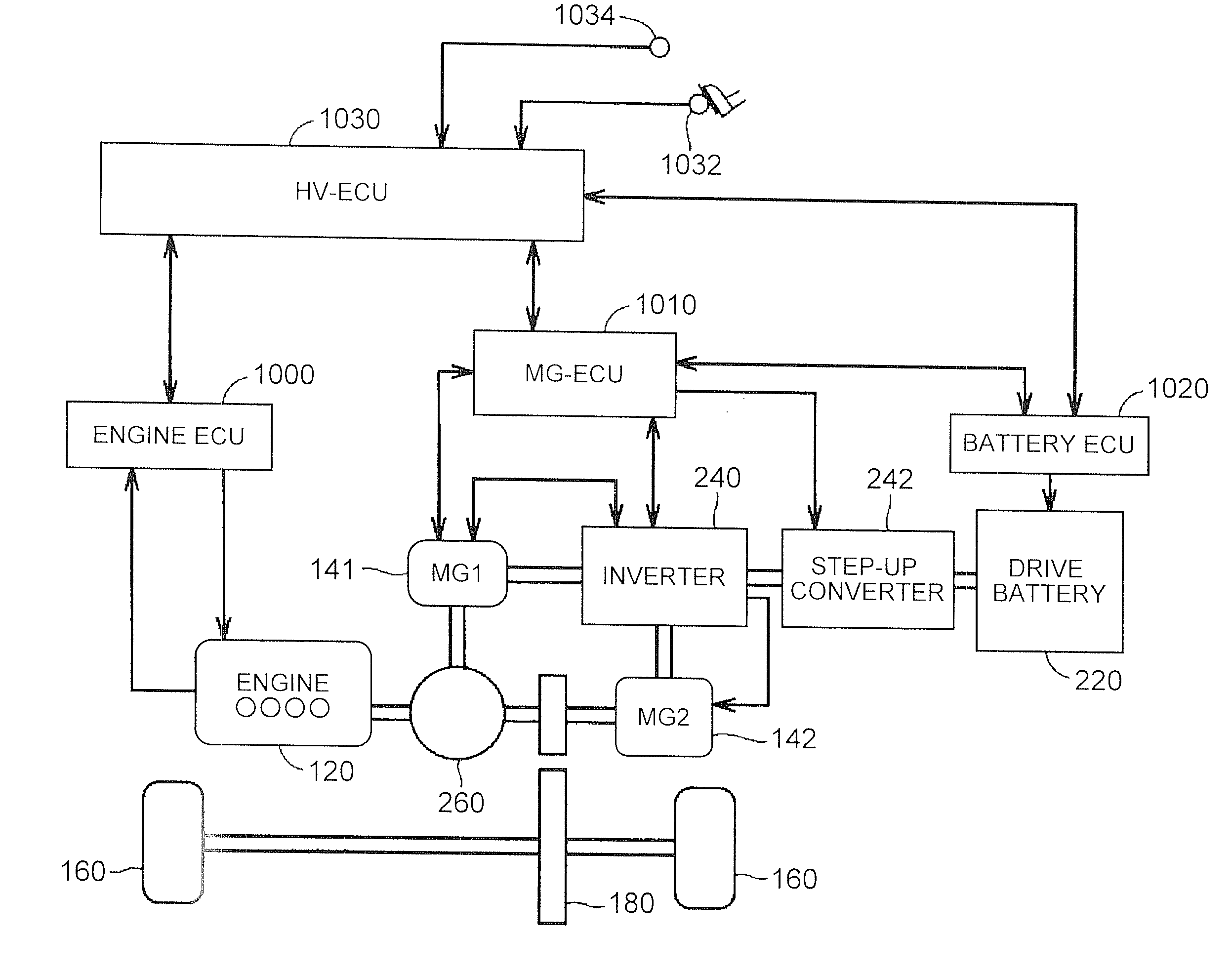
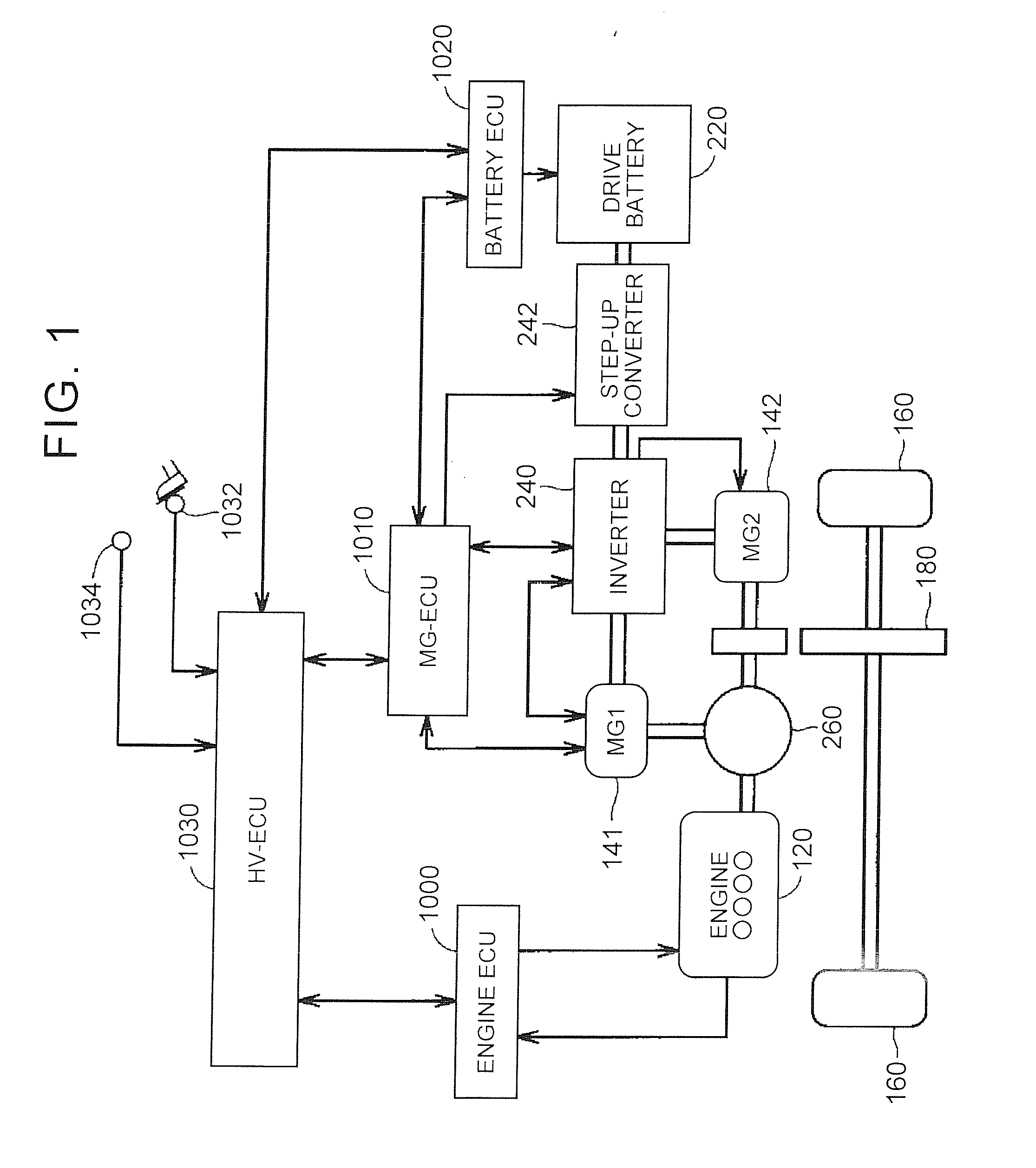
[0038]FIG. 1 is a schematic configuration view of a hybrid vehicle that is an example of a vehicle according to the invention. The hybrid vehicle includes an internal combustion engine and a motor generator, and travels by controlling a driving force from the internal combustion engine and a driving force from the motor at an optimal ratio. The invention is applicable to any vehicle as long as the vehicle includes an internal combustion engine as a driving force source.

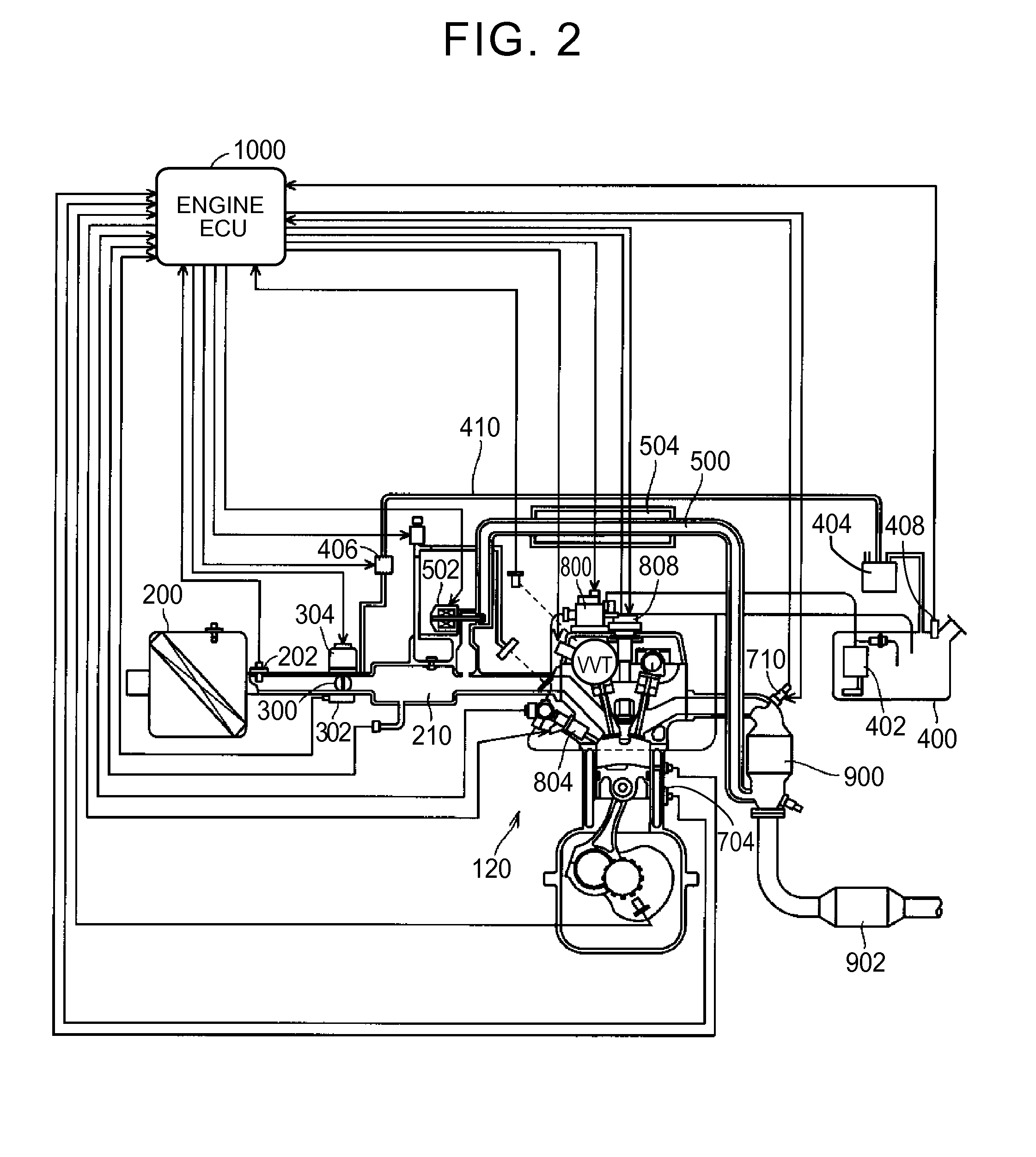
[0039]As shown in FIG. 1, the hybrid vehicle includes an internal combustion engine (engine) 120, a first motor generator (MG1) 141 and a second motor generator (MG2) 142. The engine 120 is, for example, a gasoline engine or a diesel engine, and includes a plurality of cylinders. For example, the engine 120 and the second motor generator 142 are used as driving force sources. That is, the hybrid vehicle travels on driving force from at least one of the engine 120 and the second motor generator 142. Each of the first m...

second embodiment

[0096]The schematic configuration of the vehicle according to the invention is similar to FIG. 1 and FIG. 2 except the control structure of the engine ECU 1000, so the detailed description will not be repeated.

[0097]FIG. 5 is an enlarged view of a portion corresponding to the EGR system in the vehicle according to the second embodiment of the invention.

[0098]As shown in FIG. 5, the EGR system according to the second embodiment of the invention includes pressure sensors 508, 510 instead of the temperature sensor 506 in the EGR system shown in FIG. 3.

[0099]The pressure sensor 508 is provided upstream of the EGR cooler 504. The pressure sensor 508 detects the pressure of EGR gas that is introduced into the EGR cooler 504, and outputs the detected value to the engine ECU 1000. The pressure sensor 510 is provided downstream of the EGR cooler 504. The pressure sensor 510 detects the pressure of EGR gas that is delivered from the EGR cooler 504, and outputs the detected value to the engine...

third embodiment

[0117]FIG. 7 is an enlarged view of a portion corresponding to the EGR system in the vehicle according to the invention.

[0118]As shown in FIG. 7, the EGR system according to the third embodiment of the invention includes a flow rate sensor 512 instead of the temperature sensor 506 in the EGR system shown in FIG. 3.

[0119]The flow rate sensor 512 is provided downstream of the EGR cooler 504. The flow rate sensor 512 detects the mass flow rate of EGR gas that is delivered from the EGR cooler 504, and outputs the detected value to the engine ECU 1000.

[0120]The engine ECU 1000 determines the cooling efficiency for cooling EGR gas on the basis of the detected value from the flow rate sensor 512 during EGR operation. When it has been determined that the cooling efficiency for cooling EGR gas has decreased, the display unit 1040 and the EGR system are controlled on the basis of the degree of decrease in the cooling efficiency as in the case of the first embodiment.

[0121]As described above, ...


PUM


Abstract

A vehicle includes: an exhaust gas recirculation system in an internal combustion engine for recirculating part of exhaust gas to an intake passage of the internal combustion engine via a recirculation valve; and a cooling device for cooling recirculated gas, recirculated by the exhaust gas recirculation system, with refrigerant. An engine ECU informs a failure of the cooling device with a display unit when a cooling efficiency for cooling the recirculated gas, determined on the basis of a state value of the recirculated gas, becomes lower than a first determination value. The engine ECU additionally controls an opening degree of the recirculation valve such that an amount of the recirculated gas is reduced when the cooling efficiency for cooling the recirculated gas, determined on the basis of the state value of the recirculated gas, becomes lower than a second determination value lower than the first determination value.

Description

INCORPORATION BY REFERENCE[0001]The disclosure of Japanese Patent Application No. 2013-060029 filed on Mar. 22, 2013 including the specification, drawings and abstract is incorporated herein by reference in its entirety.BACKGROUND OF THE INVENTION[0002]1. Field of the Invention[0003]The invention relates to a control device and control method for a vehicle on which an internal combustion engine is mounted as a power source and, more particularly, to control over a vehicle in the event of a failure in a cooler provided in an exhaust gas recirculation system.[0004]2. Description of Related Art[0005]There is a vehicle on which an internal combustion engine is mounted as a driving force source, the internal combustion engine including an exhaust gas recirculation (hereinafter, referred to as EGR) system that recirculates part of exhaust gas in an exhaust passage to an intake passage. The EGR system recirculates part of exhaust gas, which is emitted from the internal combustion engine, t...

Claims


Application Information

Patent Timeline
IPC IPC(8): F02D41/00
CPCF02D41/0065F02D41/221F02D2041/0067F02M25/089F02M26/15F02M26/28F02M26/49Y02T10/40
Inventor SASAKI, TOSHITAKE
Owner TOYOTA JIDOSHA KK
Learn More