Eureka AIR delivers breakthrough ideas for toughest innovation challenges, trusted by R&D personnel around the world.

Two-Part Dental Implants

a dental implant and two-part technology, applied in dental implants, dental surgery, medical science, etc., can solve the problems of poor impact strength of ceramic materials, metal ions are dissolved out of implants, and the implant is not able to bind to living tissue,

Inactive Publication Date: 2010-06-10
ZITERION GMBH
View PDF15 Cites 12 Cited by
  • Summary
  • Abstract
  • Description
  • Claims
  • Application Information

AI Technical Summary

Benefits of technology

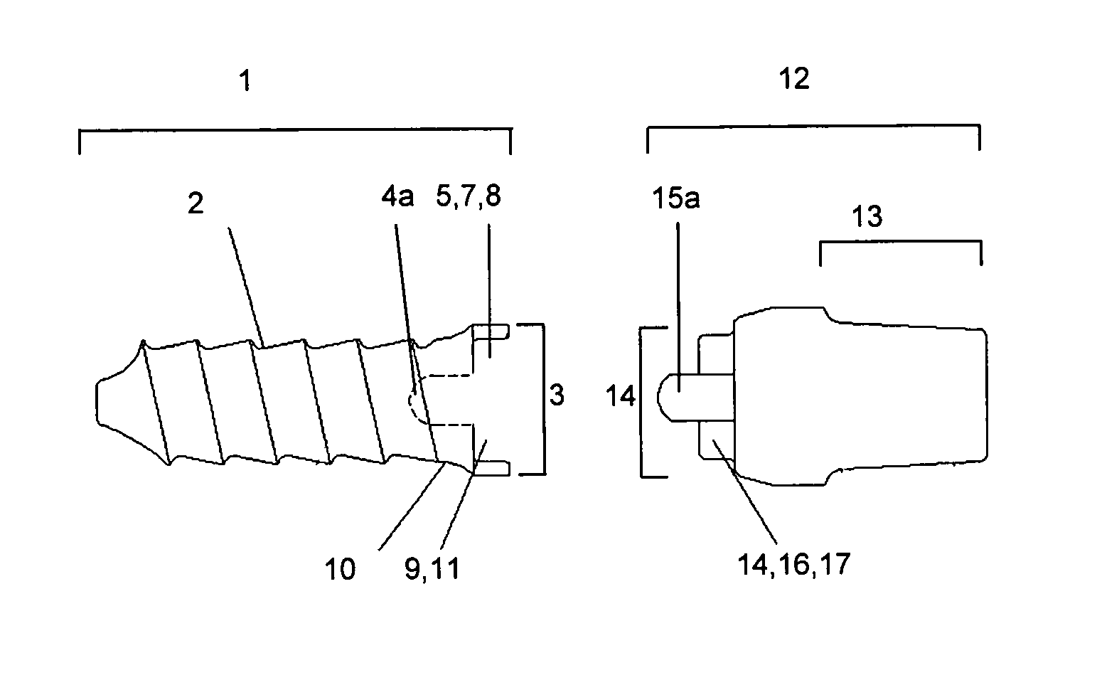
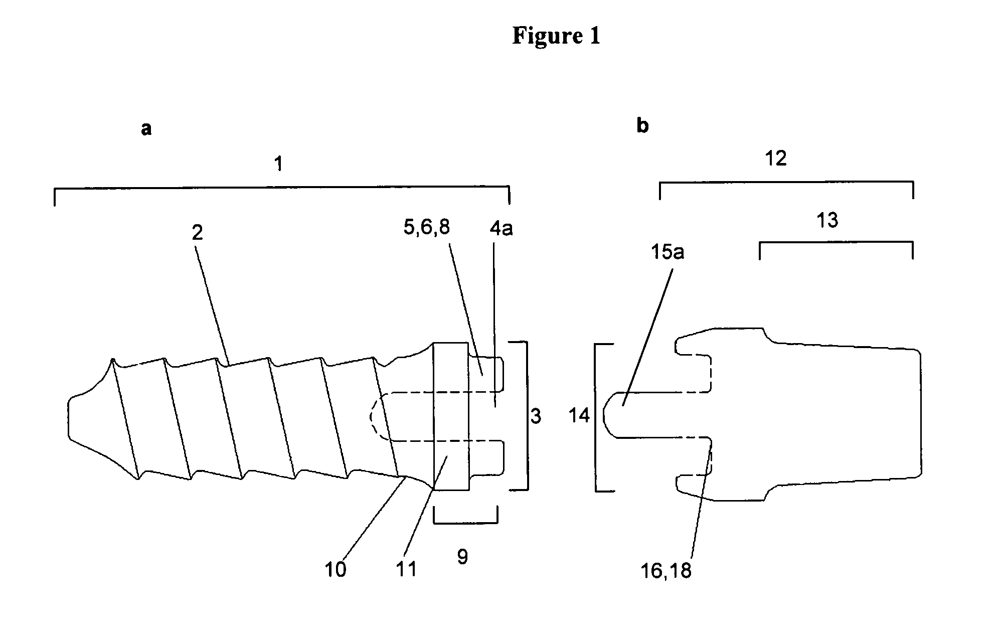
[0062]The bore through the abutment is such that a screw can be inserted through the bore which is capable of engaging the threaded part located in the indention (4) of the dental implant (1). The bore preferably comprises at least two different diameters or a conical region, with the smaller diameter bore being positioned at the apical end of the bore (19). This narrowing of the bore allows the screw head to engage the abutment (12) and prevent movement of the abutment (12) along the longitudinal axis of the hybrid two-part dental implant. Preferably, the smallest diameter of the bore (19) is between 0.5 and 4 mm, preferably 0.5, 0.6, 0.7, 0.8, 0.9, 1.0, 1.2, 1.4, 1.6, 1.8, 2.0, 2.2, 2.4, 2.6, 2.8, 3.0, 3.2, 3.4, 3.6, 3.8, 4.0 mm. It is preferred that the larger diameter is between 0.1 to 2 mm larger than the smaller diameter of the bore (19). The diameter of the smallest bore is preferably slightly larger than the outer diameter of the threaded part of the screw to be inserted.
[0077]In a preferred embodiment of the hybrid two-part dental implant of the first and second aspect of the present invention the thread-profile of said outer threaded part (2) of said dental implant (1) comprises an apical flank and a distal flank, wherein an acute angle (β) between the apical flank and the longitudinal axis is smaller than an acute angle (γ) between the distal flank and the longitudinal axis. This particular thread design leads to a secure attachment of the dental implant almost immediately after insertion of the dental implant (1) and, thus, provides reduced healing times, i.e. the abutment (12) can already be attached to the dental implant (1) after only a few days of healing.
[0085]The outer threaded part (2) will in most embodiments extend over the entire length of the part of the dental implant (1) inserted into the bone. These threads are preferably present on the cylindrical sections of the dental implant (1), while a tip, which might be attached at the apical end of the dental implant, will preferably not comprise threads. Such a tip can have any shape as long as its diameter does not extend over the diameter of the outer threaded part (2) to which it is attached, i.e. the outer diameter of the outer threaded part. Preferably the diameter of the tip does not extend beyond the inside diameter of the outer threaded part (2). The tip preferably has a round, pointed or blunt shape. As it is not always required that the entire part of the detnal implant (1) inserted into the bone is threaded, the dental implant (1) in some embodiments may comprise further parts inserted into the bone, which are not threaded. These one or more further parts are preferably located towards the apical end of the dental implant and / or towards the distal end, preferably towards the transgingival part (9). Preferably any further part which is not threaded and is inserted into the bone is also provided with a rough surface as defined above, to facilitate osseo-integration.
[0110]In another preferred embodiment the prosthetic head (13) is of conical shape. In this embodiment it has above indicated preferred widths at its base and is tapered to the top. The tapering is preferably with an angle of between 1° to 15°, e.g. 1°, 2°, 3°, 4°, 5°, 6°, 7°, 8°, 9°, 10°, 11°, 12°, 13°, 14°, or 15°. This tapering facilitates the attachment of crowns or superstructures and / or the scanning of the prosthetic head once the abutment of the present invention has been attached to the dental implant of the present invention. Such a scan can then be used, e.g. to manufacture the crown or superstructure to be attached to the prosthetic head, e.g. by CAD / CAM devices or by a dental technician, in such a way that it on one hand fits exactly to the protruding prosthetic head (13) and on the other hand will be positioned correctly with respect to the surrounding teethes.

Problems solved by technology

Metallic materials are excellent in mechanical strength, particularly in impact strength, however, they lack affinity for living tissue.
Additionally, when a metallic implant is used, metal ions are dissolved out of the implant and may be toxic to the bone and soft tissue cells surrounding the implant.
However, most ceramic materials possess poor impact strength, and are difficult and expensive to manufacture.
However, the design of a prototype injection mould is difficult and / or expensive and therefore the variability of this method, i.e. the number of different implant designs which can be produced economically is quite low.
Since in most cases a postproduction is needed, the material is not densely enough sintered at the injection moulding step, leading to defects in the material and, thus, to a high rejection rate.
However, it is an expensive method and due to the hardness of the material it is difficult to grind indentations into the implant body, such as it is needed, for example, for a conical internal connection.
Further, grinding the material leads to so-called mini-cracks (rifts), which might have an influence on the quality and stability of the implant.
Thus, with this method it is nearly impossible to provide an internal connection having securing means (antirotation), as well as to provide a screwed joint.
The two-part ceramic dental implant designs known from the prior art suffer among others from the fact that they do not yet provide a design suitable to be produced by an affordable technique known in the art, they are not amenable to processing steps by the dentist during the implantation procedure and they do not provide a durable connection between the two-parts of the dental implant.

Method used


Image

  • Two-Part Dental Implants
  • Two-Part Dental Implants
  • Two-Part Dental Implants

Examples


Embodiment Construction

[0044]Before the present invention is described in more detail below, it is to be understood that this invention is not limited to the particular methodology, protocols and materials described herein as these may vary. It is also to be understood that the terminology used herein is for the purpose of describing particular embodiments only, and is not intended to limit the scope of the present invention which will be limited only by the appended claims. Unless defined otherwise, all technical and scientific terms used herein have the same meaning as commonly understood by one of ordinary skill in the art.

[0045]Throughout this specification and the claims which follow, unless the context requires otherwise, the word “comprise”, and variations such as “comprises” and “comprising”, will be understood to imply the inclusion of a stated integer or step or group of integers or steps but not the exclusion of any other integer or step or group of integer or step. In the following passages di...


PUM


Abstract

The present invention relates in general to the field of implant dentistry, namely to to a hybrid two-part dental implant made of biocompatible ceramics and a biocompatible synthetic material, wherein said two-part medicinal device provides a basis for a crown or superstructure, which is easy to handle by a dentist. The present invention furthermore relates to the use of abutments made of biocompatible synthetic material in connection with dental implants made of biocompatible ceramics for dental prosthetics.

Description

[0001]The present invention relates in general to the field of implant dentistry, namely to a hybrid two-part dental implant made of biocompatible ceramics and a biocompatible synthetic material, wherein said two-part medicinal device provides a basis for a crown or superstructure, which is easy to handle by a dentist. The present invention furthermore relates to the use of abutments made of biocompatible synthetic material in connection with dental implants made of biocompatible ceramics for dental prosthetics.BACKGROUND OF THE INVENTION[0002]In the last decades artificial bone structures have increasingly been used for implantation in order to replace natural bones lost due to, e.g. degeneration, degradation or injury. This implantations have been performed on bones and tooth roots and have afforded good results in the remedy of defects or the recovery of functions thereof. Dental implants are commonly used to support fixed or removable prosthesis of patients when a patient's natu...

Claims


Application Information

Patent Timeline
Patent Type & Authority Applications(United States)
IPC IPC(8): A61C8/00
CPCA61C8/0012A61C8/0022A61C8/005A61C8/0069A61C8/006A61C8/0066A61C8/0054
Inventor KAHDEMANN, STEFFEN
Owner ZITERION GMBH
Why Eureka
Eureka Blog
Learn More