Eureka AIR delivers breakthrough ideas for toughest innovation challenges, trusted by R&D personnel around the world.

Method for correcting motion artifacts in magnetic resonance images

a magnetic resonance image and motion artifact technology, applied in the field of magnetic resonance imaging, can solve problems such as motion artifacts, and achieve the effect of satisfying the compensation of motion artifacts

Active Publication Date: 2010-06-10
SIEMENS HEALTHCARE GMBH
View PDF0 Cites 74 Cited by
  • Summary
  • Abstract
  • Description
  • Claims
  • Application Information

AI Technical Summary

Benefits of technology

[0015]The present invention provides a novel approach to resolve the MRI motion correction problem. The present invention takes advantage of the special structure of the motion PSF kernel for the MRI motion artifacts. The present invention provides a method that detects dominant motions from the corrupted patient image and formulates the MRI motion estimation problem as a graph-based optimization problem in order to estimate the motion for each segment in the k-space data. Specifically, the magnitude of the blur PSF, or motion PSF, for the MRI motion artifact may contain many peaks, each peak corresponding to a motion vector. A large peak in the magnitude map may represent a new or artificial image structure due to a ringing effect by a strong image structure. Hence, the inventive method first locates strong edges in the k-space data and similar image structures (i.e., ringing counterparts) from the image to estimate the locations of peaks in the PSF kernel. For each estimated motion vector, a binary variable is associated with a segment in k-space to denote if it is corrupted by this motion or not. The method combines all these binary variables in a graph and formulates the motion estimation problem as a graph-based optimization problem, which is solved by minimizing the energy associated with the graph. Experimental results show that a method in accordance with the present invention provides satisfactory compensation of motion artifacts in an MR image even when large motions of the patient or subject are involved.
[0016]In short, previous methods for compensating for motion artifacts are mainly image metric-based, and they may easily fail when the motion is large because they do not consider the structure of the motion kernal. State-of-the-art blind restoration algorithms can not be applied in such cases either because they cannot handle a complex kernel that is as large as the size of the image. The present invention provides a novel approach utilizing the image structure to decompose, or segment, the kernel into several fragments. Based on this kernel representation, determining a kernel fragment is formulated as a binary optimization problem, where each binary variable represents whether a segment in MR signals (k-space) is corrupted by a certain motion or not. The relationship between variables is established graphically and the kernel is estimated by minimizing the energy associated with the graphical models.

Problems solved by technology

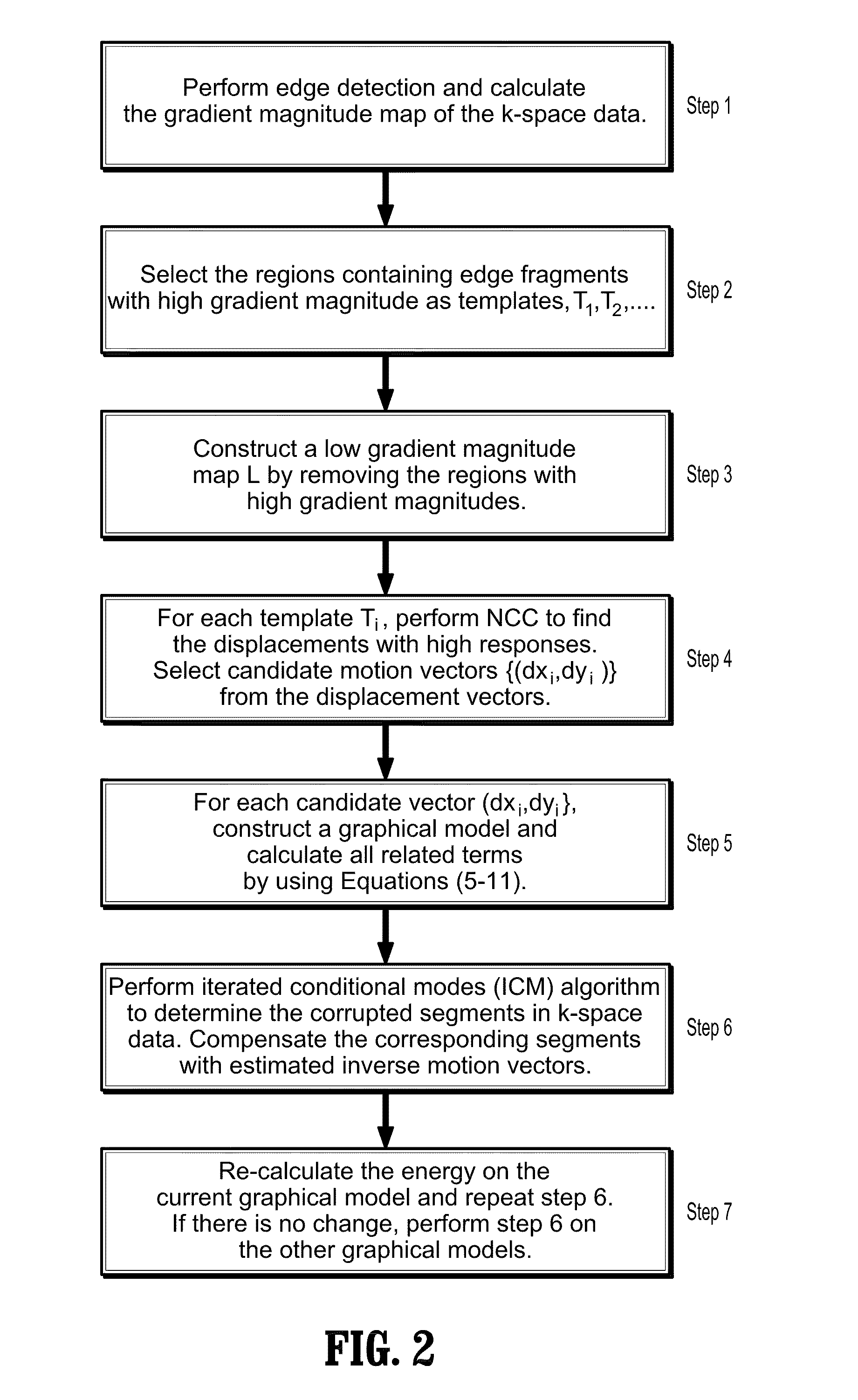
Estimating the motion vectors may further include applying a normalized cross correlation algorithm for the low gradient magnitude map to determine motion vectors in the k-space data likely causing motion artifacts.

Method used


Image

  • Method for correcting motion artifacts in magnetic resonance images
  • Method for correcting motion artifacts in magnetic resonance images
  • Method for correcting motion artifacts in magnetic resonance images

Examples


Embodiment Construction

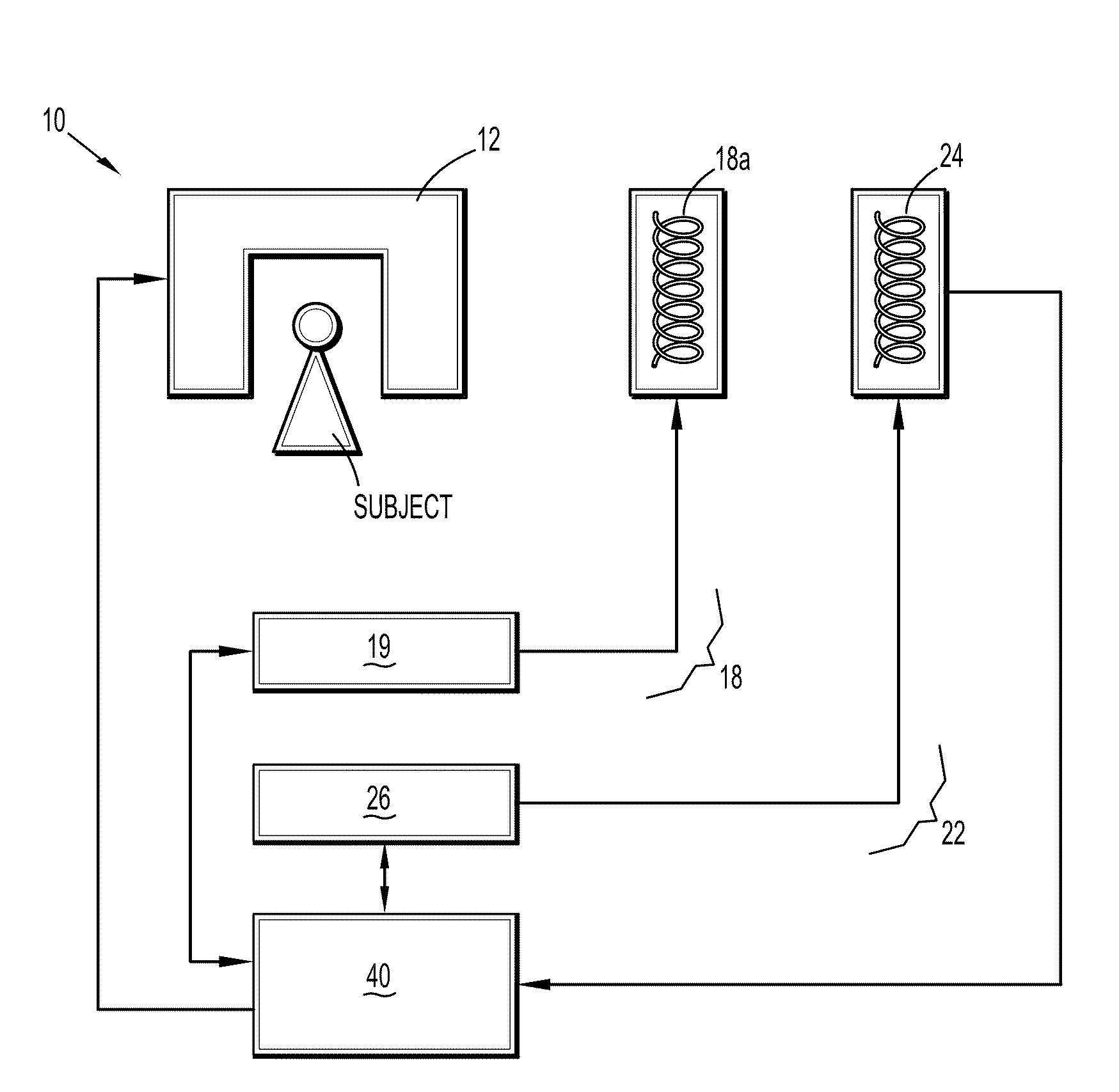
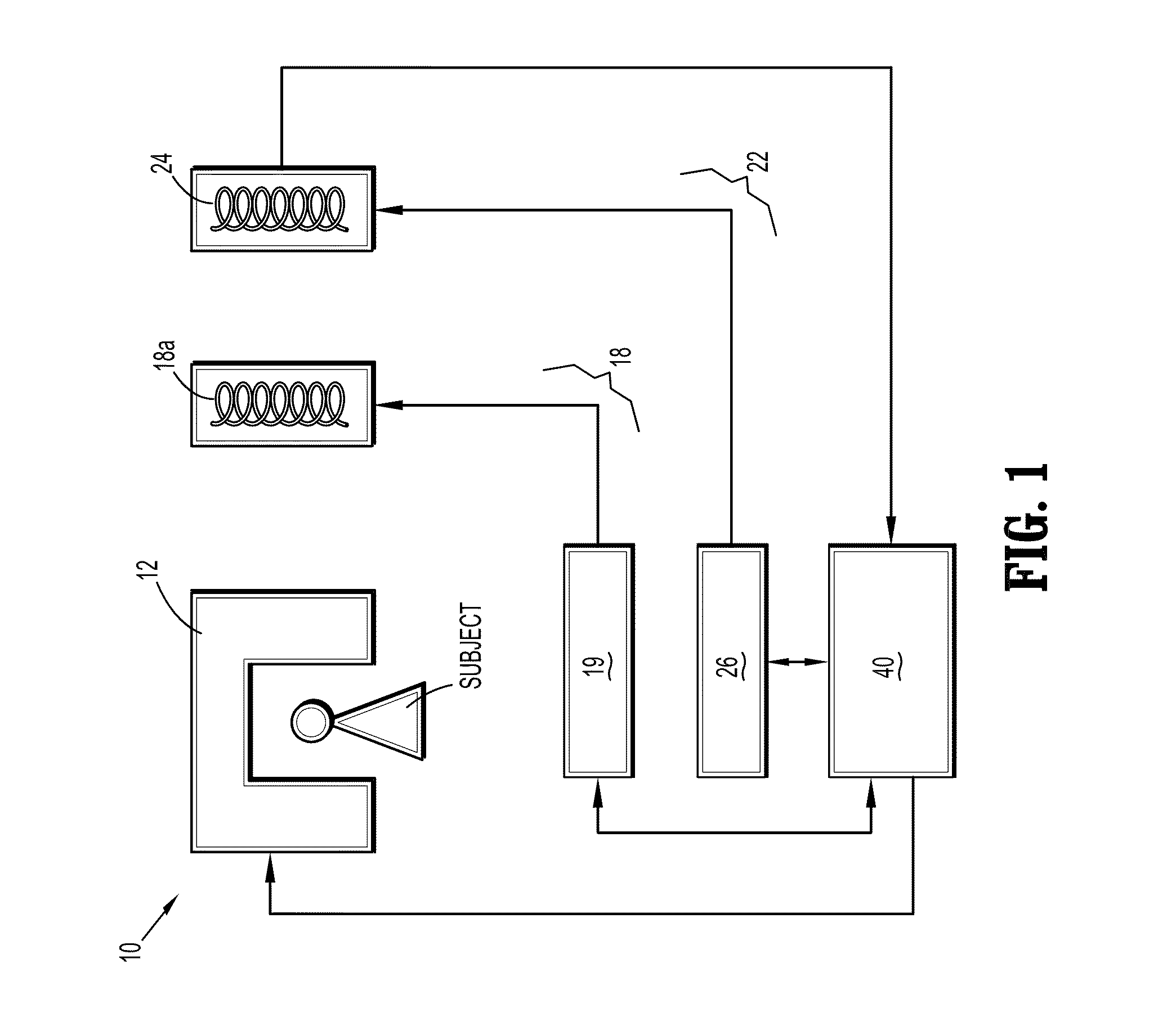
[0022]FIG. 1 is a block diagram of an MRI scanner 10 that corrects MRI motion artifacts operable in accordance with the present invention. A main magnet 12 generates a strong static magnetic field in an imaging region where the patient or the specific body part of the patient to be examined is introduced. The magnet 12 is used to polarize the patient's body part, i.e., certain atoms in the patient's body part that were previously randomly-ordered become aligned along the magnetic field. A gradient coil system 18, having a gradient coil 18a and a gradient coil control unit 19, generates a time-varying linear gradient field in respective spatial directions, x, y and z, and spatially encodes the positions of the polarized or excited atoms. An RF system 22, having an RF antenna 24 and a pulse generation unit 26, transmits a series of RF pulses to the patient's body part to excite the “ordered” atoms of the patient's body part. A control or computer system 40 coordinates the pulse genera...


PUM


Abstract

For resonance image data of an imaged subject, a method that first detects and estimates the dominant motions of k-space data (i.e., the motion vectors) and then constructs a graphical model for each estimated motion vector. The segments of the k-space that are determined to be corrupted by motion are restored by minimizing the energy associated with the corresponding graphical model. Consequently, the MR image of the imaged subject becomes free of motion artifacts.

Description

CROSS-REFERENCE TO RELATED APPLICATIONS[0001]This application claims the benefit of Provisional U.S. Patent Application Ser. No. 61 / 120,093 entitled, “Motion Correction In MRI Using Graph-Based Optimization”, filed in the name of Ti-chiun Chang, Michelle Xiao-Hong Yan, and Tong Fang on Dec. 5, 2008, the disclosure of which is also hereby incorporated herein by reference.FIELD OF INVENTION[0002]The present invention relates to magnetic resonance imaging (MRI). More particularly, the present invention relates to MRI that corrects motion artifacts.BACKGROUND OF THE INVENTION[0003]Magnetic resonance imaging (MRI) is a non-invasive diagnostic imaging procedure that uses nuclear magnetization and radio waves to produce internal images of a patient. Briefly, an MRI scanner contains magnetic coils that create a strong static magnetic field in which the patient is positioned. Certain atoms in a patient's body that were previously randomly-ordered become aligned along the magnetic field. The ...

Claims


Application Information

Patent Timeline
Patent Type & Authority Applications(United States)
IPC IPC(8): G06K9/00A61B5/055
CPCA61B5/055A61B5/7207A61B6/03G01R33/56509G01R33/5608
Inventor CHANG, TI-CHIUNFANG, TONGYAN, MICHELLE XIAOHONG
Owner SIEMENS HEALTHCARE GMBH
Why Eureka
Eureka Blog
Learn More