
System and Method of Providing Computer Resources

a technology of computer resources and system, applied in the direction of electrical apparatus contruction details, transportation items, lighting and heating apparatus, etc., can solve the problems of large footprint of facilities, difficulty in cooling server racks and cabinets, and overall cost of maintaining electronic equipmen

Inactive Publication Date: 2010-06-10
BASELAYER TECH
View PDF61 Cites 107 Cited by
  • Summary
  • Abstract
  • Description
  • Claims
  • Application Information

AI Technical Summary

Benefits of technology

[0009]In accordance with one aspect of the exemplary embodiments, a data center system can include a mobile support structure; one or more enclosures for removable electronic equipment where the enclosures are housed by the support structure; a cooling system in fluid communication with the enclosures for cooling of the electronic equipment where the cooling system is housed by the support

Problems solved by technology

These facilities often have a large footprint due to the various components necessary for maintaining the facilities, including cooling equipment.
Local building codes can effect the footprint of the facility and thus the overall cost of maintaining the electronic equipment.
Cooling of server racks and cabinets in the facilities can be problematic, particularly as processors typically produce large amounts of heat.
It has been found that for every 1 watt of power used for Information Technology, 0.5 to 2 watts of power are used for cooling the electronic components, and thus the need for cooling uses a very high percentage of the total IT power consumption.
However, such solutions suffer from drawbacks associated with the power supply needed to power the fans, as well as reliability of such fans.
Moreover, these are generally located in large facilities which further exacerbates the drawbacks.
This can lead to “hot spots” in the server room, however, much of the hot air can also mix with the cool air circulating in the room.

Method used


Image

  • System and Method of Providing Computer Resources
  • System and Method of Providing Computer Resources
  • System and Method of Providing Computer Resources

Examples


Embodiment Construction

[0035]The exemplary embodiments of the present disclosure are described with respect to an environmental management system for electronic equipment. It should be understood by one of ordinary skill in the art that the exemplary embodiments of the present disclosure can be applied to other types of management systems.

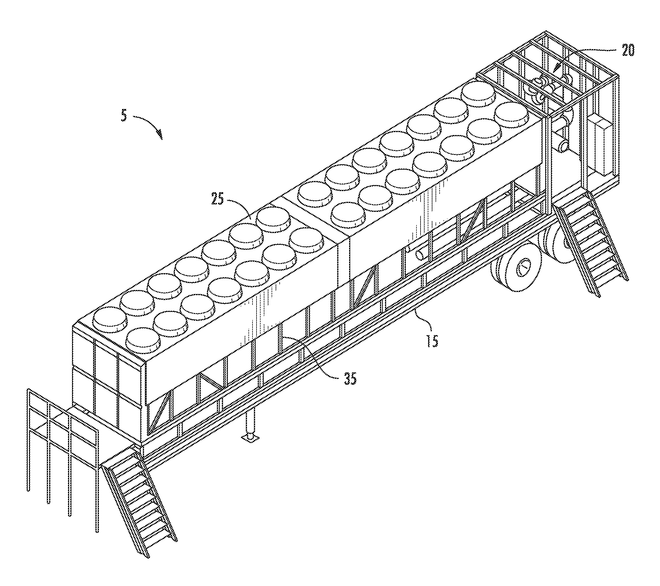
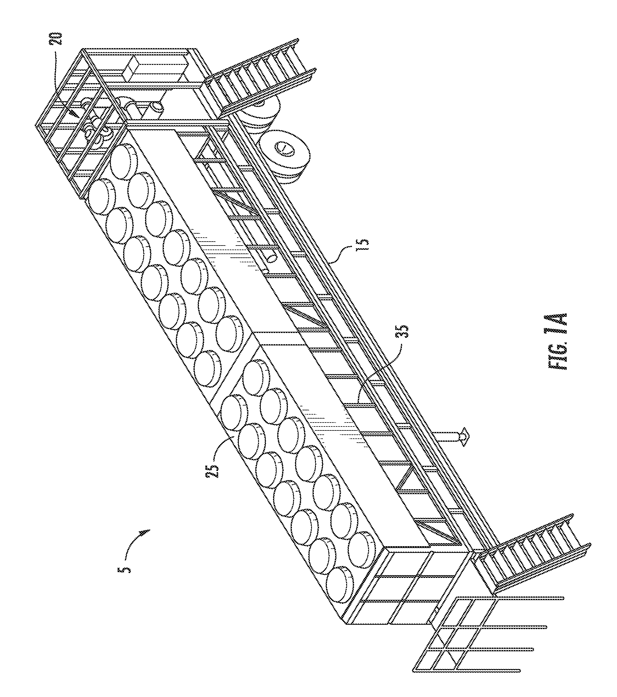
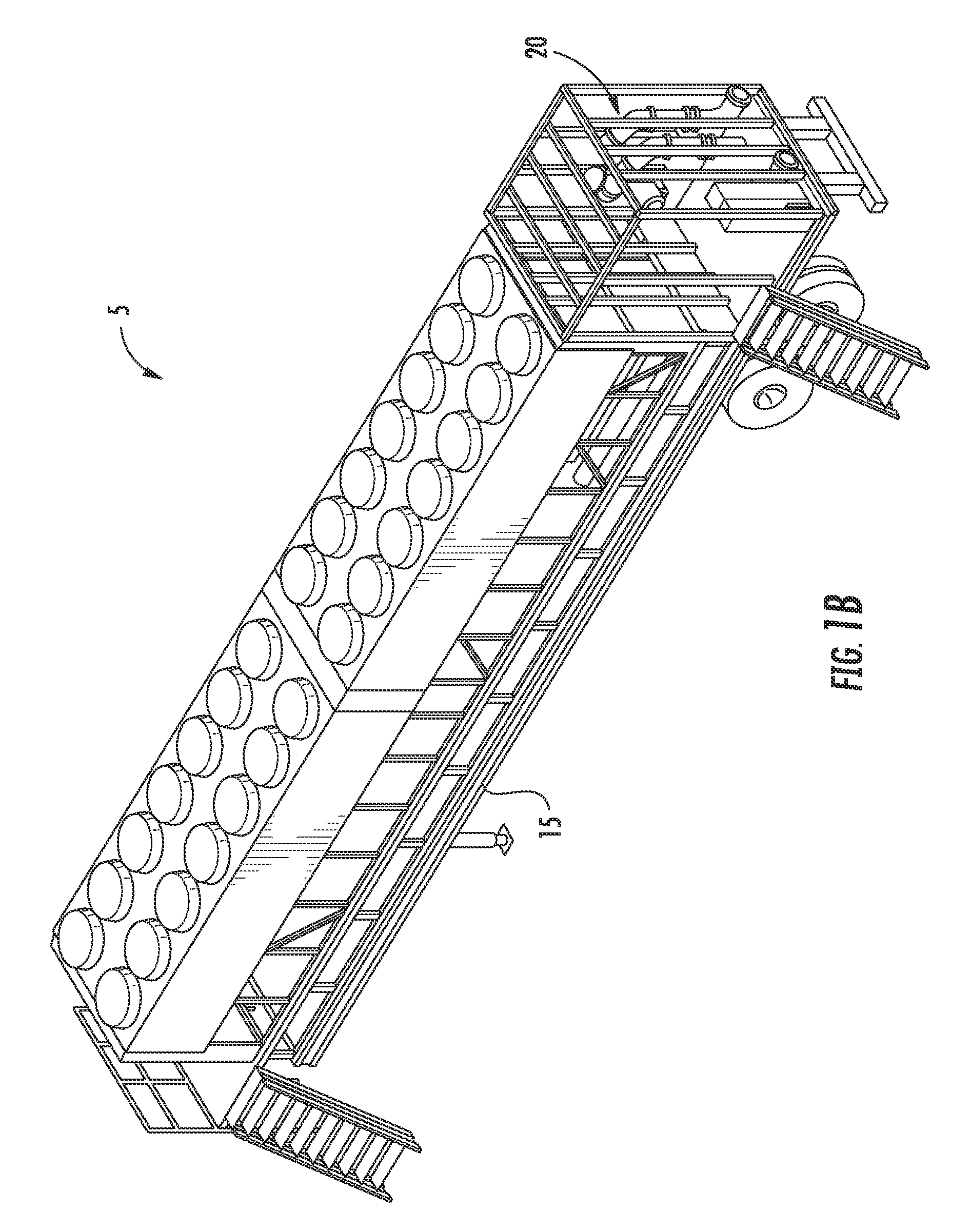
[0036]Referring to the drawings and in particular FIGS. 1A and 1B, an exemplary mobile data center system 5 is illustrated. The system 5 can include a support structure 15 which is capable of being moved to various locations, including remote locations, and then connected to a network at the new location, such as through a hardwire link, for providing computer resources. In one embodiment, the support structure 15 can be a trailer with wheels that is capable of being towed. In another embodiment, the support structure 15 can be a self-contained moving vehicle; i.e., a drivable vehicle.

[0037]The system 5 can include a power sub-system having generator 20 that provides pow...


PUM


Abstract

A data center system can include a mobile support structure; one or more enclosures for removable electronic equipment where the enclosures are housed by the support structure; a cooling system in fluid communication with the enclosures for cooling of the electronic equipment where the cooling system is housed by the support structure; and a power system operably connected to the electronic equipment and the cooling system for supplying power thereto where the power system comprises a generator housed by the support system. The mobile data center can be moved to remote locations, and the electronic equipment can be placed in communication with a network when at the remote location Other embodiments are disclosed.

Description

CROSS-REFERENCES TO RELATED APPLICATIONS[0001]This application claims the benefit of U.S. Provisional Patent application Ser. No. 61 / 119,980 filed on Dec. 4, 2008, the disclosure of which is hereby incorporated by reference.[0002]This application is related to co-pending U.S. patent application Ser. No. ______ entitled “Apparatus and Method of Environmental Condition Management for Electronic Equipment” (Attorney Docket No. 10008-17) filed contemporaneously herewith, the disclosure of which is hereby incorporated by reference.FIELD OF THE INVENTION[0003]The present application relates to providing computer resources, and particularly to a system and method for achieving the desired environmental conditions for servers and other computing devices.BACKGROUND[0004]Data centers are facilities for housing electronic equipment, such as servers. A data center can occupy one room of a building, one or more floors, or an entire building. These facilities often have a large footprint due to t...

Claims


Application Information

Patent Timeline
IPC IPC(8): F28F13/00H05K7/20
CPCF28F9/0265F28F9/028H05K7/20836H05K7/20745H05K7/20554H05K7/1497H05K7/20763
Inventor SLESSMAN, GEORGE
Owner BASELAYER TECH
Learn More