
Orthogonal cross polarization interference compensating device, demodulator, receiving station, and method of compensating cross-polarization interference

a cross-polarization interference and compensating device technology, applied in the direction of polarization/directional diversity, diversity/multi-antenna system, digital transmission, etc., can solve the problem of disadvantageous local division in terms of communication path reliability

Active Publication Date: 2010-06-03
NEC CORP
View PDF4 Cites 15 Cited by
  • Summary
  • Abstract
  • Description
  • Claims
  • Application Information

AI Technical Summary

Benefits of technology

[0017]According to the present invention, it is possible to solve the foregoing problem with the related art in which the result of integration of the integration circuit becomes indefinite when the control loop is disconnected.

Problems solved by technology

However, local division is disadvantageous in terms of the reliability of the communication path since both polarization signals are disconnected if the local oscillator is broken.
However, since phase noise from one oscillator is not related to that from the other oscillator, a phase difference originating from phase noise occurs between the other polarization component, which interferes with its own polarization, and the carrier component of the other polarization component, which is input to the orthogonal cross-polarization interference compensator.

Method used


Image

  • Orthogonal cross polarization interference compensating device, demodulator, receiving station, and method of compensating cross-polarization interference
  • Orthogonal cross polarization interference compensating device, demodulator, receiving station, and method of compensating cross-polarization interference
  • Orthogonal cross polarization interference compensating device, demodulator, receiving station, and method of compensating cross-polarization interference

Examples


first exemplary embodiment

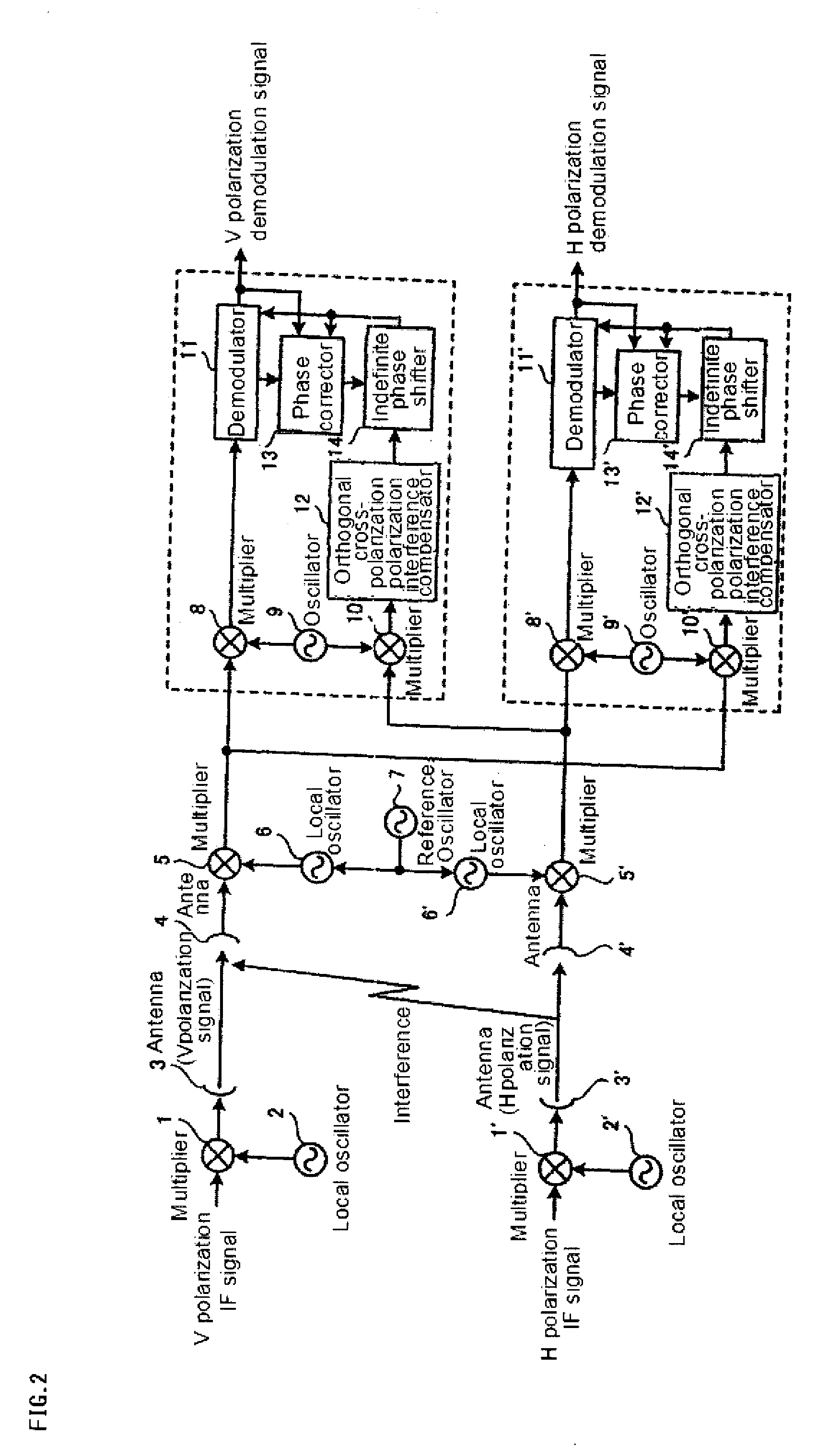
[0029]FIG. 2 is an illustration of co-channel transmission in accordance with a first exemplary embodiment of the invention, and FIG. 3 is a block diagram illustrating the configuration of an orthogonal cross-polarization interference compensating device in accordance with the first exemplary embodiment of the invention. Referring to FIG. 3, the orthogonal cross-polarization interference compensating device includes demodulator 11, orthogonal cross-polarization interference compensator 12, phase corrector 13, and infinite phase shifter 14.

[0030]The orthogonal cross-polarization interference compensating device of this exemplary embodiment will be described more fully hereinafter.

[0031]Orthogonal cross-polarization interference compensator 12 generates a compensation signal for compensating for phase noise included in an own polarization signal (i.e., an own polarization input). Demodulator 11 compensates an orthogonal cross-polarization interference of other polarization signals for...

second exemplary embodiment

[0097]In accordance with this exemplary embodiment, integration circuit 26 reduces a gain of its output when a small amount of orthogonal cross-polarization interference is present. FIG. 8 is a block diagram illustrating the configuration of orthogonal cross-polarization interference compensating device in accordance with this exemplary embodiment.

[0098]Referring to FIG. 8, orthogonal cross-polarization interference compensating device further includes multiplier 37 in addition to the configuration shown in FIG. 3. In addition, orthogonal cross-polarization interference compensating device includes control circuit 36 in place of control circuit 23.

[0099]Control circuit 36 determines whether or not orthogonal cross-polarization interference is present based on a compensation signal adjusted by infinite phase shifter 14, and if no orthogonal cross-polarization interference is present, reduces an integration signal output from integration circuit 26 to a predetermined value.

[0100]FIG. ...

third exemplary embodiment

[0107]In accordance with this exemplary embodiment, the value of an integration signal output from integration circuit 26 is reset if a small amount of orthogonal cross-polarization interference is present. The configuration of the orthogonal cross-polarization interference compensating device is substantially the same as that shown in FIG. 2 except for the internal configuration of integration circuit 26.

[0108]FIG. 10 is a block diagram illustrating the configuration of integrating circuit 26 in accordance with the second exemplary embodiment of the invention. Referring to FIG. 10, integration circuit 26 includes adder 30 and flip-flop 31.

[0109]Control circuit 23 clears the value of the integration signal by clearing a value maintained by flip-flop 31 to a predetermined value if no orthogonal cross-polarization interference is present. Meanwhile, control circuit 23 can use a converging signal, which indicates a converging operation previously described in the first exemplary embodi...


PUM


Abstract

An orthogonal cross-polarization interference compensating device for solving the problem tin which integration contents of an integration circuit are indefinite when a control loop is cut. An orthogonal cross-polarization interference compensator generates a compensation signal for compensating phase noise included in an own polarization signal. A demodulator compensates for orthogonal cross-polarization interference based on the compensation signal for the phase noise included in the own polarization signal. An error detector generates an error signal indicating phase difference between the own polarization signal compensated by the demodulator and a proper own polarization signal. A phase noise phase detector generates a differential signal indicating phase difference between the own polarization signal and other polarization signals based on the compensation signal and the error signal. An integration circuit integrates the differential signal and generates an integration signal. An infinite phase-shifter adjusts the compensation signal based on the integration signal. A control circuit determines whether or not orthogonal cross-polarization interference is present based on the compensation signal adjusted by the infinite phase-shifter, and adjusts the integration value indicated by the integration signal to be a predetermined value when there is no orthogonal cross-polarization interference.

Description

TECHNICAL FIELD[0001]The present invention relates to an orthogonal cross-polarization interference compensating device or a cross-polarization interference canceller (XPIC), a demodulator, a receiving station, and a method of compensating cross-polarization interference, and more particularly, relates to an orthogonal cross-polarization interference compensating device or a cross-polarization interference canceller (XPIC), a demodulator, a receiving station, and a method of compensating cross-polarization interference, which uses co-channel transmission in a wireless communication device.BACKGROUND ART[0002]Recently, wireless communication devices are using a co-channel transmission mode, in which different pieces of information are sent on two polarization signals that have the same frequency and different phases. The two polarization signals are referred to as a vertical polarization signal and a horizontal polarization signal and are sometimes referred to as V polarization signa...

Claims


Application Information

Patent Timeline
IPC IPC(8): H04B15/00H04B1/10
CPCH04B7/10H04B7/002H01Q21/245H03D3/002H03D7/165H04B1/126H04L27/0014H04L2027/0067
Inventor KAWAI, MASAHIRO
Owner NEC CORP
Learn More