
Quick-positioning screw assembly

a screw and assembly technology, applied in the direction of screws, threaded fasteners, manufacturing tools, etc., can solve the problems of requiring labor to pick up and pack, waste of time and labor, and manual installation, and achieve the effect of quick and accurate installation and avoiding falling of any component parts

Inactive Publication Date: 2010-06-03
HANWIT PRECISION IND LTD
View PDF6 Cites 20 Cited by
  • Summary
  • Abstract
  • Description
  • Claims
  • Application Information

AI Technical Summary

Benefits of technology

[0006]The present invention has been accomplished under the circumstances in view. It is therefore the main object of the present invention to provide a quick-positioning screw assembly, which allows quick and accurate installation to secure a first plate member to a second plate member by means of a mounting system, avoiding falling of any component parts.

Problems solved by technology

Picking up the positioning screw assembly for installation manually wastes much time and labor.
Further, it requires much labor to pick up and pack the fallen Teflon rings F. Further, a special storage place is necessary to keep the packed Teflon rings F in place.

Method used


Image

  • Quick-positioning screw assembly
  • Quick-positioning screw assembly
  • Quick-positioning screw assembly

Examples


Embodiment Construction

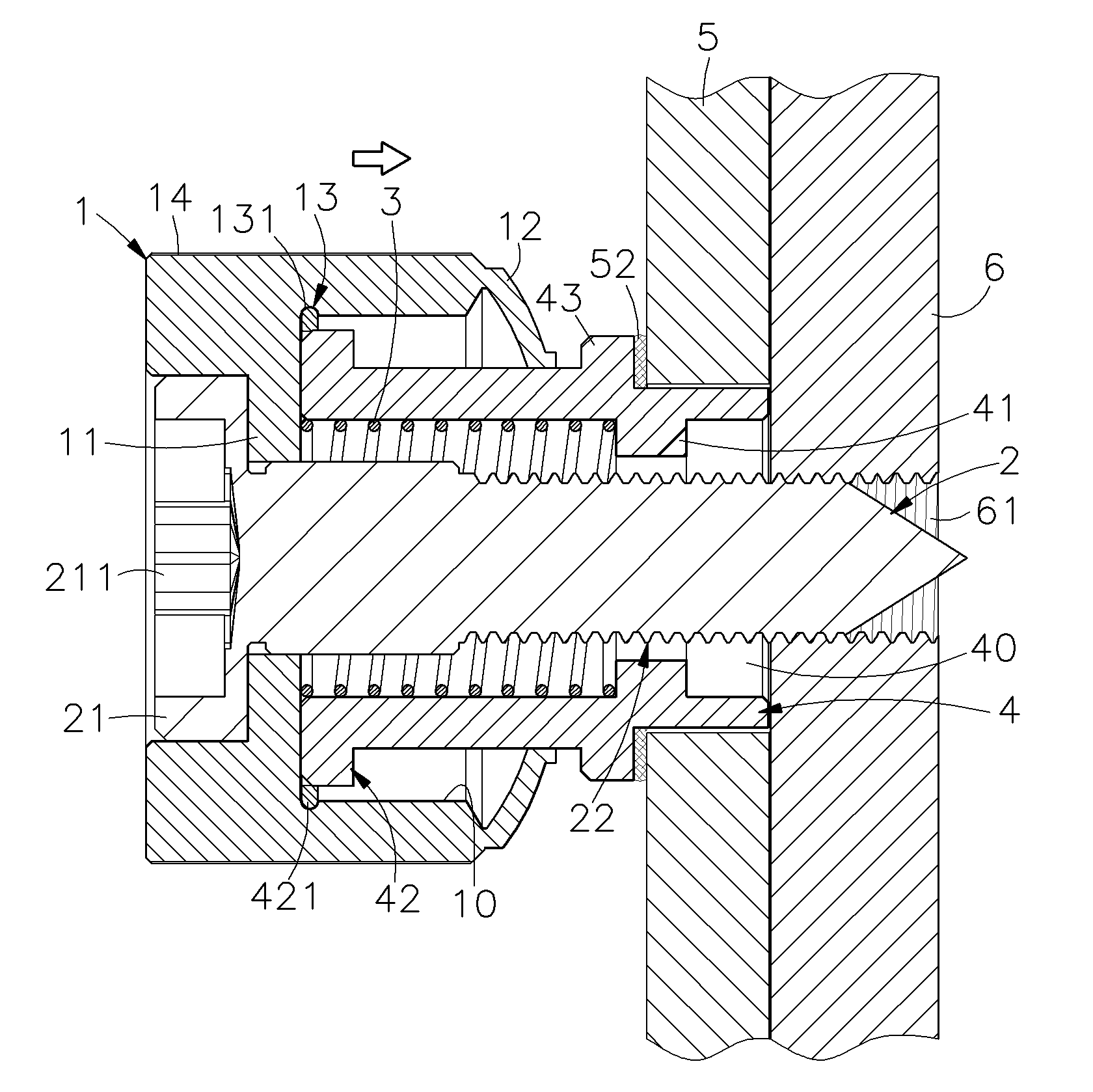
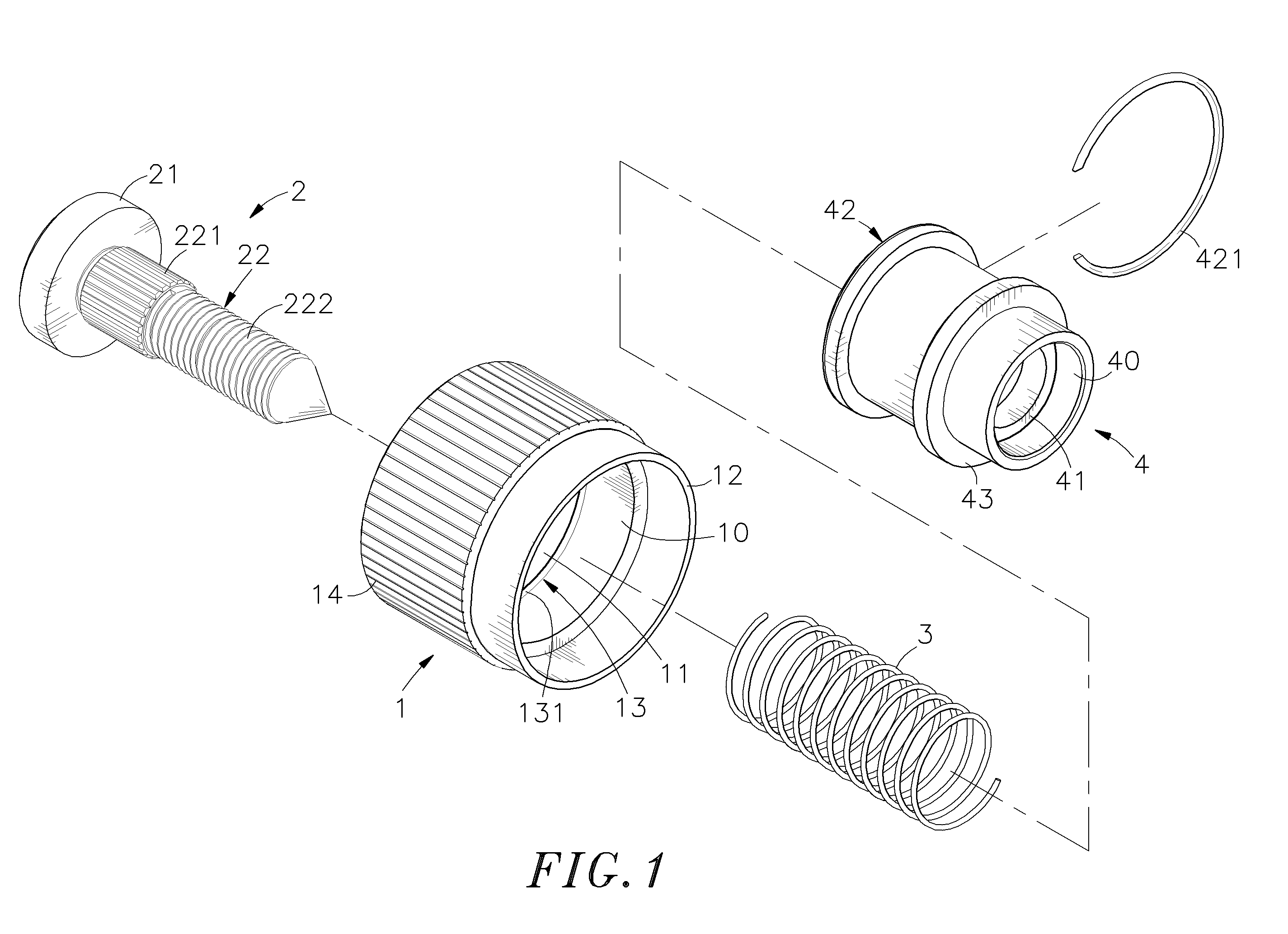
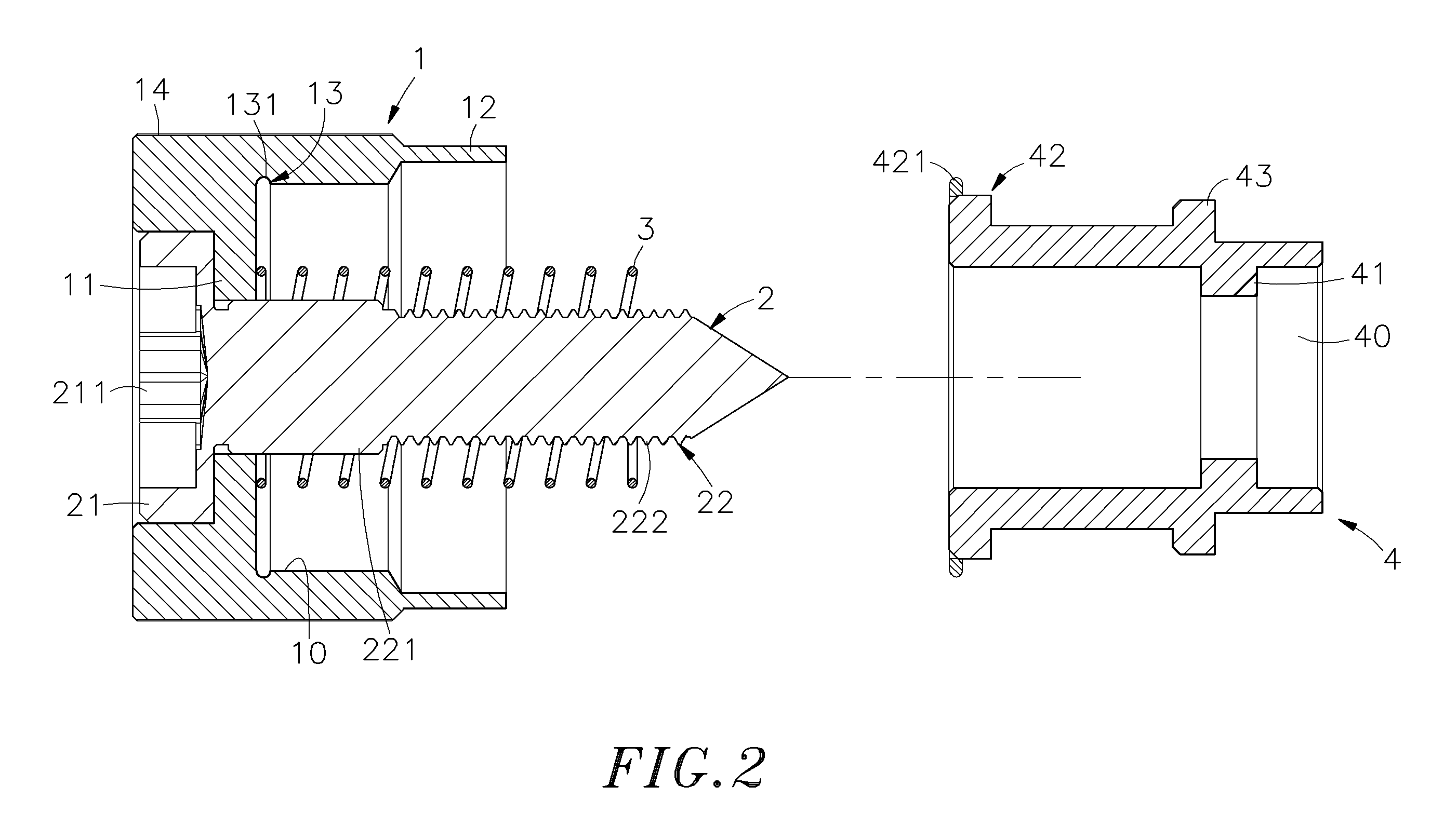
[0017]Referring to FIG. 1, a quick-positioning screw assembly in accordance with a first embodiment of the present invention is shown comprised of a cap 1, a screw 2, an elastic member 3 and a mounting socket 4.

[0018]The cap 1 has a through hole 10 extending through top and bottom sides thereof, an inside annular flange 11 suspending in the through hole 10, a relatively thinner front extension cap wall 12 axially forwardly extending the bottom side of the peripheral wall, and a locating means 13, for example, a locating groove 131 extending around the border area between the inside annular flange 11 and the peripheral wall of the cap 1.

[0019]The screw 2 has a head 21 supported on the inside annular flange 11 in the cap 1, and a screw body 22 inserted through the through hole 10 of the cap 1. The screw body 22 includes a toothed shoulder 221 formed integral with the bottom wall of the head 21 and press-fitted into the tight engagement with the inside annular flange 11 of the cap 1, a...


PUM

PropertyMeasurementUnit
frictionaaaaaaaaaa
inner diameteraaaaaaaaaa
speedaaaaaaaaaa

Abstract

A quick-positioning screw assembly includes a cap having an inside annular flange and a locating groove or locating rib extending around the inside wall, a mounting socket bonded to a mounting through hole of a first plate member and having a top positioning flange extending around the periphery and detachably forced into engagement with the locating groove or locating rib of the cap, a screw press-fitted into the inner diameter of the inside annular flange of the cap for threading into a screw hole on a second plate member to secure the first plate member to the second plate member, and a compression spring mounted in the cap around the screw and stopped between the inside annular flange of the cap and an inside annular flange of the mounting socket.

Description

BACKGROUND OF THE INVENTION[0001]1. Field of the Invention[0002]The present invention relates to a screw assembly and more particularly, to a quick positioning screw assembly that can quickly and accurately be installed in a first plate member by a mounting system for securing the first plate member to a second plate member.[0003]2. Description of the Related Art[0004]Fastening plate members in a stack is an application of stacking attachment technique to fully utilize the space. With respect to the functioning of the power drive or speed-adjustment unit of a machine tool, when a machine base failed or an adjustment of the speed of the machine is necessary, a movable plate member will be detachably mounted on a housing of the power drive or speed-adjustment unit. Screw bolts are commonly used to secure the movable plate member to the machine tool. When unfastening screw bolts to dismount the movable plate member from the machine tool, the associating lock nuts may fall from the scre...

Claims


Application Information

Patent Timeline
Patent Type & Authority Applications(United States)
IPC IPC(8): B23P11/00
CPCY10T29/53978F16B5/0208
Inventor CHIU, MING-CHUNG
Owner HANWIT PRECISION IND LTD
Learn More