
Method for disassembling and assembling hollow shaft assembly of high-speed rail wheel rolling mill

A technology of wheel rolling mill and disassembly method, which is applied in metal processing equipment, metal processing, manufacturing tools, etc., can solve the problems of low disassembly and assembly operation efficiency, shorten the service life of parts, affect production efficiency, etc., and improve disassembly and assembly efficiency. Safety of disassembly and assembly, ensure accuracy and safety and reliability, and realize the effect of automatic control

Active Publication Date: 2021-12-10
MAANSHAN MAGANG JINXI RAIL TRANSPORT EQUIP
View PDF6 Cites 1 Cited by
  • Summary
  • Abstract
  • Description
  • Claims
  • Application Information

AI Technical Summary

Problems solved by technology

[0003] Four bearings are installed on the hollow shaft to assist the rotation of the hollow shaft. In order to roll the wheel to a certain size, the roller surface of the spoke plate roller will exert huge unequal pressure on the red steel wheel during the rolling process of the wheel, and the hollow shaft bearing will be affected Axial load and radial load, after a period of use, will cause the bearing of the hollow shaft to wear or be damaged, and the web roll cannot rotate normally, seriously affecting the rolling quality of the wheel, and even causing the hollow shaft of the web roll to fail to rotate, seriously affecting production efficiency. At this time, the hollow shaft bearing must be replaced to make the wheel rolling mill work normally and meet the technological requirements of wheel rolling
[0004] Due to the complex structure of the hollow shaft assembly and the complex process of bearing replacement and disassembly, there is currently no standardized operating procedure and sequence, which makes the disassembly operation inefficient and easily causes damage to spare parts. In addition, there is a hollow shaft on the left and right sides of the rolling mill. Replacing a bearing on a hollow shaft requires 48 hours of downtime, seriously affecting production efficiency
[0005] For some parts that are difficult to disassemble, they may even be unable to be disassembled during disassembly, and must be cut off, which will cause certain damage to adjacent parts; When reassembling, accurate positioning is required, such as the key connection positioning between the hollow shaft casing and the eccentric shaft casing, the locking and positioning of the lock nut on the hollow shaft, and the coordinated positioning of the eccentric shaft and the frame. The traditional method requires Positioning is performed by repeatedly tapping the hammer and continuously moving the vehicle, which is time-consuming and labor-intensive, and sometimes causes certain damage to adjacent parts
The traditional disassembly method of the hollow shaft assembly shortens the service life of the parts, and there are certain safety hazards in the disassembly process

Method used


Image

  • Method for disassembling and assembling hollow shaft assembly of high-speed rail wheel rolling mill
  • Method for disassembling and assembling hollow shaft assembly of high-speed rail wheel rolling mill
  • Method for disassembling and assembling hollow shaft assembly of high-speed rail wheel rolling mill

Examples


Embodiment Construction

[0056] In order to make the purpose, technical solutions and advantages of the embodiments of the present invention more clear, the technical solutions in the embodiments will be clearly and completely described below in conjunction with the drawings in the embodiments of the present invention. The following embodiments are used to illustrate the present invention , but not to limit the scope of the present invention.

[0057] In the description of the present invention, it should be noted that the terms "upper", "lower", "front", "rear", "left", "right", "vertical", "inner", "outer" etc. The indicated orientation or positional relationship is based on the orientation or positional relationship shown in the drawings, and is only for the convenience of describing the present invention and simplifying the description, rather than indicating or implying that the referred device or element must have a specific orientation, or in a specific orientation. construction and operation, ...


PUM


Abstract

The invention discloses a method for disassembling and assembling a hollow shaft assembly of a high-speed rail wheel rolling mill, and belongs to the technical field of use and maintenance of high-speed rail wheel rolling mill equipment. The disassembling and assembling method comprises the following steps: a radial plate roller, a radial plate roller shaft, a radial plate roller driving oil cylinder and an eccentric shaft at one end of a hollow shaft are dismantled; after a lubricating pipeline, a cooling pipeline and all connecting lines are dismantled, the hollow shaft is lifted out to be separated from a rack; a radial plate roller shaft box body and an eccentric shaft box body are dismantled, and an oil cylinder, an oil cylinder accessory, a pull rod and a circumferential supporting component are sequentially dismantled in the axial direction of the other end of the hollow shaft; after the hollow shaft is vertically placed, a locking nut, a bearing and accessories on the hollow shaft are dismantled; and all parts on the hollow shaft are reversely mounted according to the above steps. The method has the beneficial effects that operation specifications are provided for disassembly and assembly of the hollow shaft assembly, disassembly and assembly are conducted in the axial direction of the hollow shaft in the manner that disassembly is conducted from outside to inside and assembly is conducted from inside to outside through a designed tool, the disassembly and assembly efficiency is improved, the installation cost is saved, and the mounting precision, safety and reliability are ensured.

Description

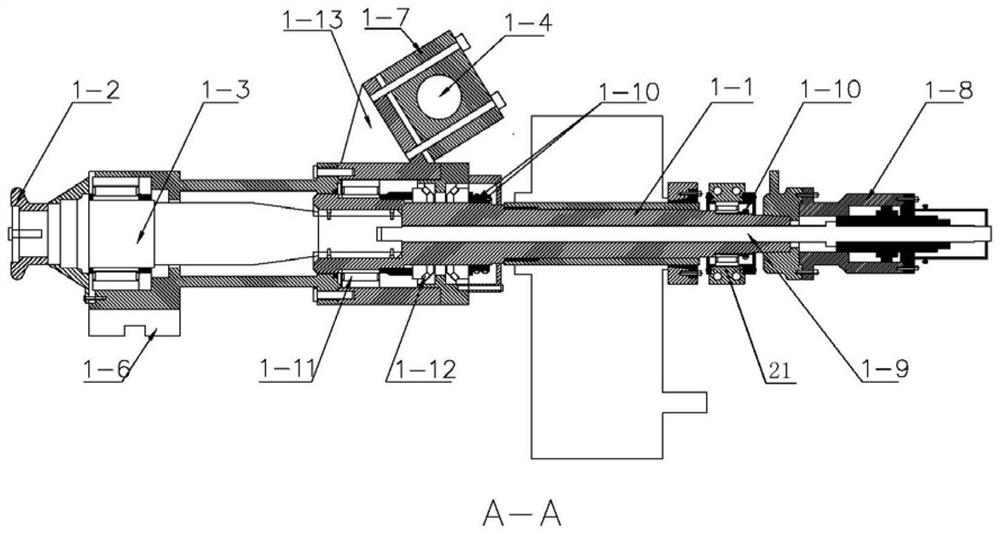
technical field [0001] The invention relates to the technical field of use and maintenance of high-speed rail wheel rolling mill equipment, in particular to a method for disassembling and assembling a hollow shaft assembly of a high-speed rail wheel rolling mill. Background technique [0002] The core equipment of wheel rolling is the wheel rolling mill. The wheel rolling is mainly completed through the mutual cooperation between the left and right web rolls, left and right inclined rolls, left and right guide rolls, upper centering rolls, lower centering rolls and main rolls of the rolling mill. The left and right web rollers are driving rollers, the left and right inclined rollers, left and right guide rollers, upper centering rollers, lower centering rollers and main rollers are driven rollers, and the rotation of the left and right web rollers is driven by the left and right driving motors respectively. The rotation drives the reduction box to rotate, the output shaft of...

Claims


Application Information

Patent Timeline
Patent Type & Authority Applications(China)
IPC IPC(8): B23P19/04
CPCB23P19/04
Inventor 杨西马灵辛昌杰
Owner MAANSHAN MAGANG JINXI RAIL TRANSPORT EQUIP
Learn More