Quick loading and unloading construct for heavy construct and manufacturing method thereof

A structure, heavy-duty technology, applied in construction, hoisting device, building structure, etc., can solve problems such as hidden safety hazards, low construction efficiency, manual assistance, etc., to achieve reliable force, reduce equipment and construction costs, and reduce occupation time. Effect

Active Publication Date: 2020-11-10
CCCC WUHAN HARBOR ENG DESIGN & RES
View PDF15 Cites 1 Cited by
  • Summary
  • Abstract
  • Description
  • Claims
  • Application Information

AI Technical Summary

Problems solved by technology

Existing heavy-duty structures are usually connected by lifting lugs and cables, but this solution is a flexible connection that requires manual assistance during installation and positioning, resulting in low construction efficiency and greater safety hazards

Method used


Image

  • Quick loading and unloading construct for heavy construct and manufacturing method thereof
  • Quick loading and unloading construct for heavy construct and manufacturing method thereof
  • Quick loading and unloading construct for heavy construct and manufacturing method thereof

Examples


Embodiment 1

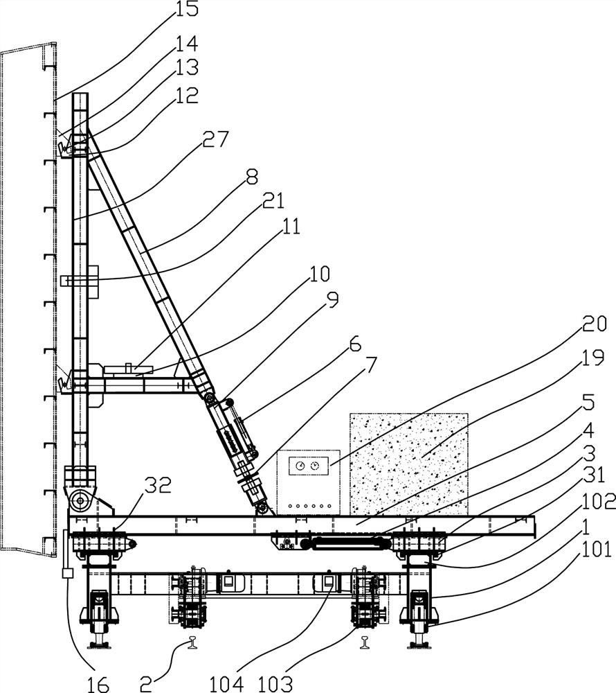
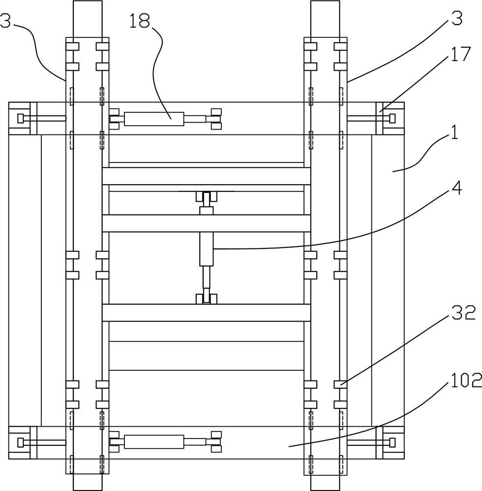
[0052] Such as figure 1 , 2 , 11~15, a fast loading and unloading structure for a heavy-duty structure, which includes a plurality of load-bearing devices fixed on the heavy-duty structure 15, the distance between the multiple load-bearing devices is a fixed value; the heavy-duty structure described in this example The structure 15 includes underground immersed pipes or steel end seal doors of corridors; fabricated shear walls, fabricated beams, fabricated columns or other fabricated components; the number of bearing devices can be 2 to 4. For example, on the prefabricated column, two load-bearing devices are arranged vertically, while on the prefabricated beam, two load-bearing devices are arranged horizontally, and four rectangular ones are set on the prefabricated shear wall. The distance between the carrying devices can also be set in multiple groups according to the size of the heavy-duty structure 15, such as 50cm, 100cm or 200cm apart.

[0053] The bearing device is u...

Embodiment 2

[0079] A method for manufacturing the above-mentioned quick loading and unloading structure for heavy-duty structures, comprising the following steps:

[0080] S1, fixing the relative positions of a plurality of backing plate nuts 23 with a mould, and connecting the connection frame 144 with the backing plate nuts 23;

[0081] S2. Determine the centroid position of the heavy-duty structure 15; obtain the centroid position of the heavy-duty structure 15 through design software or check calculation.

[0082] S3, arrange the reinforcement structure of the heavy-duty structure 15, place the connection frame 144 near the centroid of the heavy-duty structure 15, and connect the connection frame 144 to the reinforcement structure directly or through the connection rib welding;

[0083] S4, fill the backing plate nut 23 with foam sealing plug 29, and form the hole 26 for receiving the connecting bolt 25 by the foam sealing plug, the top of the foam sealing plug 29 is flush with the to...


PUM


Abstract

The invention provides a quick loading and unloading structure for a heavy construct and a manufacturing method thereof. The quick loading and unloading structure comprises a plurality of bearing devices fixedly arranged on the heavy construct, and the distance between every two adjacent the bearing devices is fixed. The bearing devices are used for being detachably connected with bearing bases fixedly arranged on a loading and unloading trolley; the positions of the bearing bases correspond to the positions of the bearing devices one to one; the bearing devices can be quickly separated from the bearing bases and are located at the positions close to the center of mass of the heavy construct. By using the scheme of the fixed-distance bearing devices, the time for hanging the device can beshortened, the heavy construct can be quickly and conveniently hung onto the loading and unloading trolley, the loading and unloading trolley can conveniently adjust the position and posture of the heavy construct, and the heavy construct is convenient to quickly and precisely install. And in addition, the fixed-distance bearing devices can be commonly used for the heavy constructs of different types and specifications, so that the loading and unloading trolley is less adjusted, the device and construction cost is greatly reduced, and the safety hidden risk is greatly reduced.

Description

technical field [0001] The invention relates to the field of installation and disassembly of heavy structures, in particular to a fast loading and unloading structure of heavy structures and a manufacturing method thereof. Background technique [0002] The heavy-duty structures referred to in this example include structures that are difficult or inconvenient to carry by manpower, such as underground sinking pipes or steel end seal doors of corridors; prefabricated shear walls, prefabricated beams, prefabricated columns or other prefabricated structures Components; large integrated glass curtain wall units, etc. Taking the immersed tube steel end seal door as an example, the current installation mostly adopts the traditional construction method: first install the corbel and steel beam, and finally rely on the installed components to use the spreader and chain hoist to position and install the end seal door, which is also a lot of heavy-duty construction. The main installatio...

Claims


Application Information

Patent Timeline
IPC IPC(8): B66F9/06B66F9/075B66F9/12B66F9/22E04G21/16E04G21/18
CPCB66F9/06B66F9/0755B66F9/07577B66F9/07554B66F9/12B66F9/075B66F9/22E04G21/162E04G21/1841
Inventor 谢小琴梁丰刘斌李海方阮明华纪岩王虎臣
Owner CCCC WUHAN HARBOR ENG DESIGN & RES
Why Eureka
Try Eureka