Eureka AIR delivers breakthrough ideas for toughest innovation challenges, trusted by R&D personnel around the world.

Method for Manufacturing an Object from a Sandwich Structure Having a Reinforced Corner and an Object of this Type

a technology of sandwich structure and object, which is applied in the field of manufacturing and reinforcing a corner in an object made from a sandwich structure, can solve the problems of low strength of the object at the location of the corner, significant weight increase, and only slight increase in local stiffness and strength

Active Publication Date: 2010-05-27
FITS HLDG
View PDF2 Cites 13 Cited by
  • Summary
  • Abstract
  • Description
  • Claims
  • Application Information

AI Technical Summary

Benefits of technology

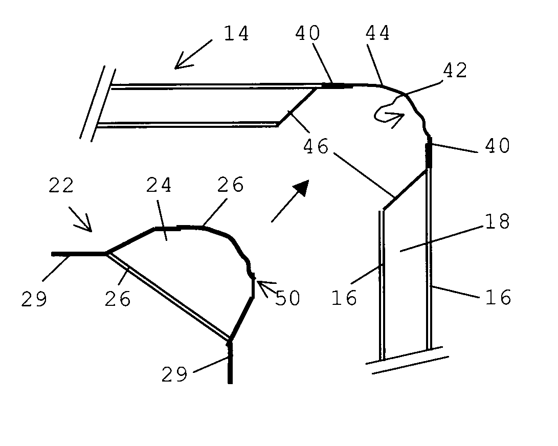
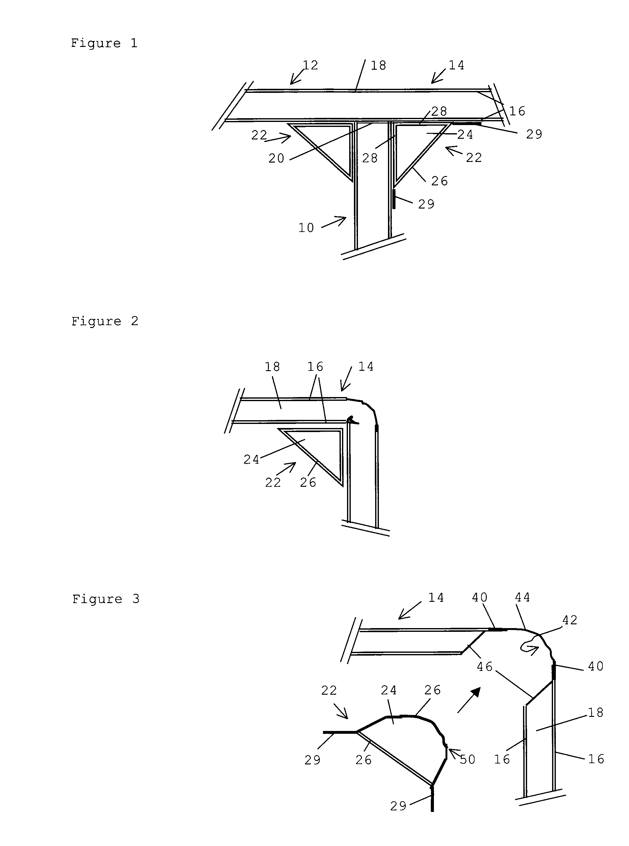
[0020]The exposed side of the core part (the surface which does not contact the object parts or, expressed in yet another way, the surface turned away from the cover layer of the object parts) may have any suitable shape and is provided with an additional fibre-reinforced thermoplastic layer. The additional fibre-reinforced thermoplastic layer can be applied separately. Preferably, this layer is connected to the core part. A core part having a fibre- reinforced thermoplastic layer which is connected thereto as a cover layer is also referred to below as a reinforcing element. The additional fibre-reinforced thermoplastic layer is subsequently connected to the respective cover layer of the object parts. Advantageously, the additional fibre-reinforced thermoplastic layer overlaps the cover layer over a certain distance. The presence of the additional fibre-reinforced thermoplastic layer and the connection thereof to a cover layer of the object parts, which enclose an angle, reinforces the corner. In particular, the strength and stiffness thereof are increased. Advantageously, the additional fibre-reinforced thermoplastic layer is connected to the plastic cover layer of the object parts. In the case of a thermoplastic cover layer, the additional thermoplastic layer can easily be connected with the aid of heat and pressure, for example by pressing or welding, or with the aid of adhesive. The addition of material, in particular the additional fibre-reinforced thermoplastic layer, and the connection of the layers to one another results in a reinforcement of the corner, while the advantageous weight properties of the sandwich structures are retained.
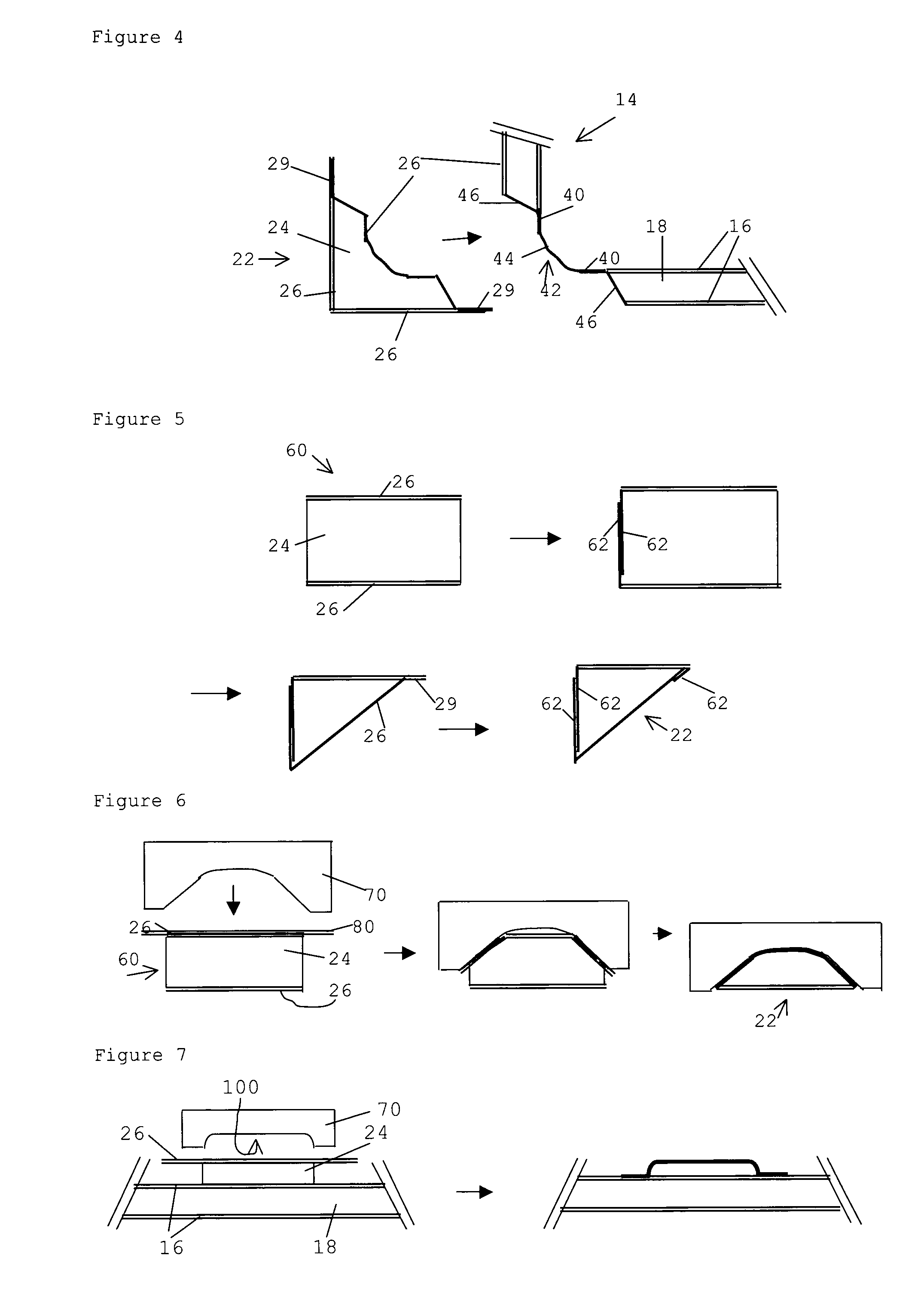
[0028]With this preferred embodiment of the method according to the invention, a corner is produced in a sandwich panel and a depression is produced at the corner position at the same time. For this purpose, for example a hot die can be used in the case of a thermoplastic core layer, which hot die deforms the respective cover layer and locally compresses the material of the core layer to form a more compact layer. If necessary, the respective cover layer may be interrupted beforehand, for example by means of cutting, milling or sawing. Advantageously, this depression extends up to the fibre-reinforced thermoplastic cover layer. Subsequently, the depression formed in this manner is filled with a reinforcing element. One side (=surface portion) of the reinforcing element fits into the depression. For further reinforcement of the corner, a further additional fibre-reinforced thermoplastic layer may be provided between this side and the bottom and the walls (if desired with the exception of the head ends) of the sandwich structure which delimit the depression. This further additional fibre-reinforced thermoplastic layer is then connected to a cover layer, most preferably a fibre-reinforced thermoplastic cover layer of the sandwich structure using one or more of the above-described connecting techniques, such as pressing, (induction) welding or gluing. The additional fibre-reinforced thermoplastic layer of the reinforcing element is also connected to the cover layers delimiting the depression. The depression may be provided both on the outside and on the inside of the corner to be formed. Advantageously, the additional fibre-reinforced thermoplastic cover layer in the finished product extends from the (fibre-reinforced thermoplastic) cover layer on a surface of the sandwich structure to the other cover layer at the opposite surface. This improves the (bending) stiffness. In a reinforcing element, the additional fibre-reinforced thermoplastic layer is applied to the respective side of the core part thereof beforehand. It will be understood that it is also possible to use a separate thermoplastic core part and separate additional fibre-reinforced thermoplastic layer.
[0034]With this preferred embodiment, an interruption, such as an incision having a length corresponding to an (imaginary) folding line is provided in the (optionally fibre-reinforced) thermoplastic cover layer, which is situated opposite the at least one fibre-reinforced thermoplastic cover layer of the sandwich structure, advantageously at or near the position of the corner to be formed. Thereafter, the edges of the incision are deformed by applying pressure and heat, for example using a hot die. In this case, the edges of the cover layer, which delimit the interruption, are bent towards the other fibre-reinforced thermoplastic cover layer and the core layer is compressed at the same time. If desired, an additional fibre-reinforced thermoplastic reinforcing layer can be laid over the incision, prior to the deformation step, and be deformed at the same time. Thus, a depression is formed, the walls of which are at least partially delimited by the deformed edges of the cover layer. Preferably, the depression extends up to the fibre-reinforced thermoplastic cover layer, which thus forms the bottom of the depression. Thereafter or at the same time, the parts of the object on the sides of the depression are bent around the (imaginary) folding line to form a desired corner. Said bending operation may be performed in such a manner that the walls of the depression are moved towards one another, but also in such a manner that the walls of the depression are moved away from one another. In the first case, an angled sandwich panel is produced, in which the depression is situated on the inside of the corner. In the second case, the depression is situated on the outside of the corner. Subsequently, a thermoplastic core part and at least one fibre-reinforced thermoplastic layer, either as separate parts or as an integrated reinforcing element, are positioned in the depression at the location of the corner. The latter embodiment is preferred. Thus, the reinforcing element fits into this depression. The reinforcing element is connected to the sandwich structure, for example by means of welding or gluing. In this manner, the stiffness / strength of the corner and the impact strength are increased by the addition of material, in particular the fibre-reinforced thermoplastic cover layer. An angled sandwich panel produced in this manner thus has a high impact strength and a good transmission of force, while the increase in weight is only very small. This is particularly important for aeroplane trolleys, galleys and luggage bins.

Problems solved by technology

A drawback of such objects known in the art is the low strength thereof at the location of the corner as a result of the folded fibre-reinforced top layer.
Such a filling operation not only results in a significant increase in weight (although such sandwich structures are in fact intended for lightweight applications), but also increases the (local) stiffness and strength only slightly.
The abovementioned joints result in a significant increase in weight or a considerable local reduction in strength and stiffness.

Method used


Image

  • Method for Manufacturing an Object from a Sandwich Structure Having a Reinforced Corner and an Object of this Type
  • Method for Manufacturing an Object from a Sandwich Structure Having a Reinforced Corner and an Object of this Type
  • Method for Manufacturing an Object from a Sandwich Structure Having a Reinforced Corner and an Object of this Type

Examples


Embodiment Construction

[0018]To this end, the method for manufacturing and reinforcing a corner in an object made from a sandwich structure, comprising a core layer (which is arranged between two cover layers, at least one of which is a cover layer made of plastic, according to an embodiment of the invention) comprises the steps of: producing an object comprising a corner between two object parts; positioning a thermoplastic core part and an additional fibre-reinforced thermoplastic layer in the corner, which thermoplastic core part has a shape adapted to the corner, in such a manner that the additional fibre-reinforced thermoplastic layer substantially covers the exposed surface of the core part; and connecting a cover layer of the sandwich structure to the additional fibre-reinforced thermoplastic cover layer.

[0019]With the method according to an embodiment of the invention, an object which has a corner between two object parts thereof is first formed from a sandwich structure. The sandwich structure co...


PUM

PropertyMeasurementUnit
Fractionaaaaaaaaaa
Thicknessaaaaaaaaaa
Shapeaaaaaaaaaa

Abstract

An exemplary method for manufacturing and reinforcing a corner in an object made from a sandwich structure, having a thermoplastic core layer (18), which is arranged between two cover layers (16), at least one of which is a plastic cover layer, which method includes the steps of: producing an object including a corner between two object parts; positioning a thermoplastic core part (24) and an additional fibre-reinforced thermoplastic layer (26) in the corner, which thermoplastic core part has a shape adapted to the corner, in such a manner that the additional fibre-reinforced thermoplastic layer (26) substantially covers the exposed surface of the core part (24); and connecting a cover layer (16) of the sandwich structure to the additional fibre-reinforced thermoplastic layer (26).

Description

CROSS-REFERENCE TO RELATED APPLICATION[0001]This national phase application claims priority to provisional application no. NL 1033895, filed 25 May 2007 PCT application no. PCT / NL2008 / 000133, international filing date 21 May 2008, which is incorporated herein by reference.BACKGROUND[0002]1. Technical Field[0003]According to a first aspect, the invention relates to a method for manufacturing and reinforcing a corner in an object made from a sandwich structure, comprising a core layer, which is arranged between two cover layers, at least one of which is a plastic cover layer.[0004]2. Description of the Related Art[0005]A method for manufacturing an object from a thermoplastic sandwich structure comprising object parts which are at an angle is known in the art. European patent 431,669 for example discloses a method for manufacturing an object from a thermoplastic sandwich material, in which the normals of at least two surfaces or object parts are at an angle to one another. This known ...

Claims


Application Information

Patent Timeline
IPC IPC(8): F16S1/02B29C53/06B32B7/04B29C70/24
CPCB29C53/063Y10T428/24628B29C66/43B29C66/43421B29C66/43441B29K2101/12B29K2105/04B29K2105/06B29L2009/00B29C66/1142Y10T428/17B29C65/5071B29C65/4815Y10T156/1025Y10T156/1051Y10T428/239B29C66/727Y10T156/1046Y10T156/1005B29C65/00B29C66/7212B29C66/72143B29C66/72141B29C66/71B29C66/721B29C66/73921B29C66/72525B29C65/3636B29C65/18B29C65/3432B29C65/3436B29C65/3632B29C65/3676B29C65/02B29C65/3476B29C65/3484B29C65/3684B29C66/8322B29C66/712B29C66/112B29C66/72325B29C66/723B29C66/72321B29C66/1122B29C66/114B29C66/1162B29C66/1222B29C66/1224B29C66/12441B29K2307/04B29K2309/08B29K2277/10B29K2023/04B29K2023/10B29K2069/00B29K2027/06B29K2071/00B29K2079/085B29K2081/06B29K2305/00B29K2023/06B29K2023/12
Inventor DE GROOT, MARTIN TH.
Owner FITS HLDG
Why Eureka
Eureka Blog
Learn More