
Packaging for fused fiber devices for high power applications

a fused fiber and high-power technology, applied in the field of packaging for fused fiber devices, can solve the problems of fragile fiber optic components, fragile optical materials of the optical fiber, and need to be protected, so as to and reduce the risk of damag

Active Publication Date: 2010-05-27
GOOCH & HOUSEGO
View PDF9 Cites 4 Cited by
  • Summary
  • Abstract
  • Description
  • Claims
  • Application Information

AI Technical Summary

Benefits of technology

[0008]The Present Inventors have recognized that a significant reliability aspect in packaging designs for fused-fiber devices with thin substrates for dissipating internally generated heat is obtained by avoiding substrate slots which as noted above carry the risk of failure due to thermal stressing. The Present Inventors have further recognized that improved reliability packaging configurations such as conventional D-shaped and the related slab-shaped substrates support optical power levels which are generally limited primarily because of limited thermal conductivity between the affixment on or proximate to both ends of the fused portion of the device and the exterior of the packaging. Moreover, the Present Inventors have recognized that for fused-fiber devices to reliably transmit higher optical power levels, new packaging configurations are needed that provide improved thermal conductivity between the affixment and the exterior of the housing.
[0009]The Present Inventors have developed new concave shaped slotless substrate designs that provide a reduced distance from the inside substrate surface to the outside substrate surface that is substantially constant throughout the substrate and have a high surface area to volume ratio as a result. Embodiments of the invention include packaged fused-fiber devices that are well adapted for high power applications and the accompanying levels of optical loss that result in heating and that are passively cooled, and thus may not require active cooling due to their ability to more efficiently conduct internal heat to their external environment. However, embodiments of the invention may also be used in active cooling arrangements.
[0010]The packaged fused-fiber device comprises a fused-fiber device having at least one input fiber and at least one output fiber, and a fused portion between the input fiber and output fiber. A concave shaped substrate comprises an inside surface and an outside surface, wherein a minimum distance from the inside surface to the outside surface is substantially constant throughout the substrate. As defined herein and generally recognized a “concave shape” is a shape comprising lines or segments that form an angle between them that is less than 180 degrees, thus curving in or hollowed inward.

Problems solved by technology

Most fiber optic components, such as fused-fiber devices, are fragile components and need to be protected from environmental influences and other abuses both during use and during production.
Generally, fiber optic components, and in particular fused-fiber devices, are sensitive to environmental influences because the optical material of which the optical fibers are made is very fragile.
In the case of fused-fiber devices, the fused region is particularly sensitive to adverse environments which can influence the quality of the optical material of the fused-fiber device and / or the signals transmitted through the fused-fiber device.
In operation of the fused-fiber device a portion of the optical power launched into the device is unavoidably converted into heat because of internal leakage of light power into its packaging through optical loss.
For high optical power applications, the resulting temperature rise caused by power loss can cause internal heating of the packaged device sufficient to degrade the packaging and / or compromise the performance of the device.
Both power handling and reliability are generally significantly affected by the packaging of the device.
As a result the substrate material may not provide optimum thermal conductivity.
However, slotted thin substrates have increased thermal stressing of the slot resulting from thermal coefficient mismatch between the affixment and the substrate materials.
Due to the resulting potential for fracture of the substrate proximate to the slot under conditions of temperature cycling or significant internal generation of heat, slotted thin substrates may be unsuitable for applications involving high optical power where long term reliability is needed.
In addition, substrate 113 generally has planar surfaces and does not generally attempt to match the shape of the fiber as this would tend to result in a slotted topology.
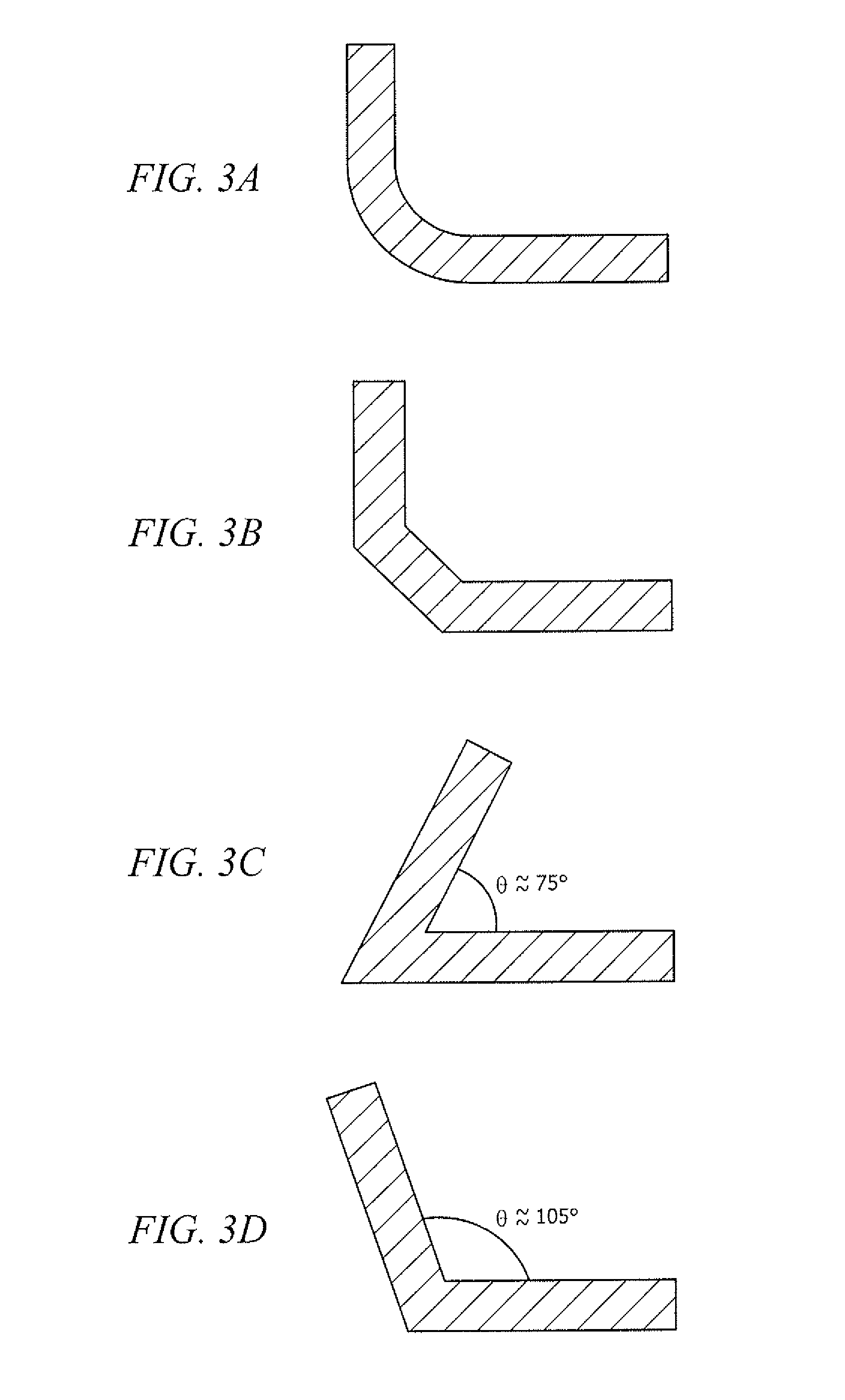
Angles significantly less than 75 degrees, such 60 degrees or less, can begin to become susceptible to thermally induced fracture as described above that is characteristic of thin slotted substrates.
In particular, angles less than 60 degrees are generally too slot-like to carry acceptable risk of the above reliability problems associated with thermal stressing, while angles greater than 105 degrees tend to lead to an impractical flattened device.

Method used


Image

  • Packaging for fused fiber devices for high power applications
  • Packaging for fused fiber devices for high power applications
  • Packaging for fused fiber devices for high power applications

Examples


examples

[0030]The following non-limiting Examples serve to illustrate selected embodiments of the invention. It will be appreciated that variations in proportions and alternatives in elements of the components shown will be apparent to those skilled in the art and are within the scope of embodiments of the present invention.

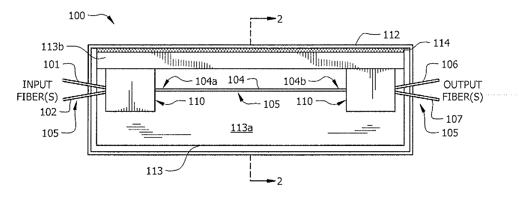
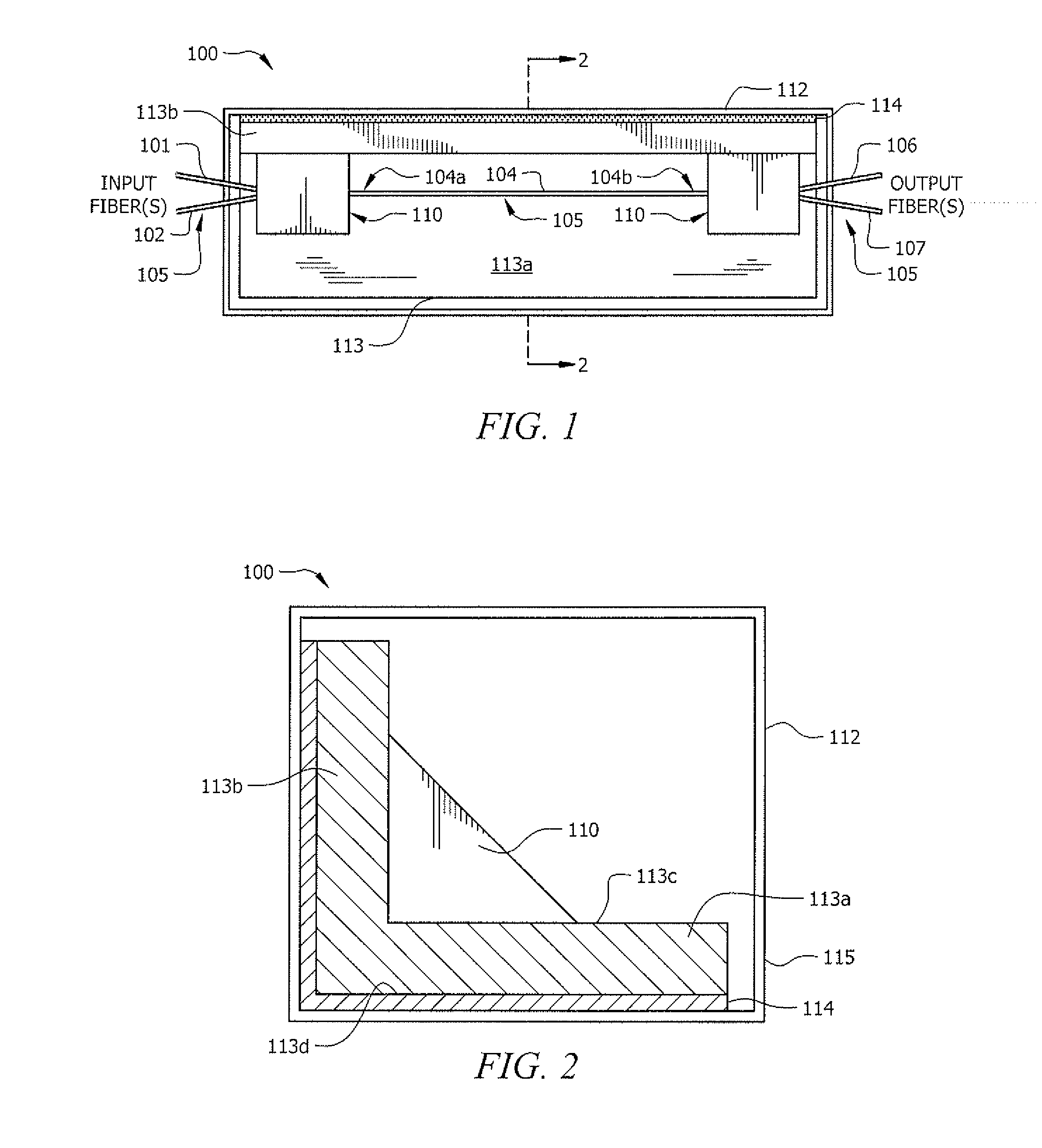
[0031]Heat dissipation capabilities for a packaged fused-fiber device according to an embodiment of the invention based on the packaged fused-fiber device 100 shown in FIGS. 1 and 2 (L-shaped substrate and rectangular housing) were tested to compare the cooling of a conventional packaged fused-fiber device comprising a slab-shaped substrate in a rectangular sectioned housing, when used in conjunction with a typical passive external heat sink. The performance of the respective fused-fiber devices were modelled based on thermal imaging data. The packaged fused-fiber device according to an embodiment of the invention was found to be about 2.6 times more efficient at heat di...


PUM


Abstract

A packaged fused-fiber device includes a fused-fiber device having at least one input fiber and at least one output fiber, and a fused portion between the input fiber and output fiber. A concave shaped substrate has an inside surface and an outside surface, wherein a minimum distance from the inside surface to the outside surface that is generally set by the substrate thickness is substantially constant throughout the substrate. An affixment material secures the first and second ends of the fused portion to the inside surface of the substrate. A thermally conductive housing is in thermal contact with the outside surface of the substrate. In one embodiment the substrate has an L-shaped cross section and the housing is a hollow housing that has a rectangular cross section.

Description

FIELD[0001]This invention relates to packaged fused fiber devices and more specifically packaged fused fiber devices having substrate configurations for enhanced cooling.BACKGROUND[0002]Most fiber optic components, such as fused-fiber devices, are fragile components and need to be protected from environmental influences and other abuses both during use and during production. In particular, fused-fiber devices are formed by fusing and tapering two or more optical fibers together. Generally, fiber optic components, and in particular fused-fiber devices, are sensitive to environmental influences because the optical material of which the optical fibers are made is very fragile. In the case of fused-fiber devices, the fused region is particularly sensitive to adverse environments which can influence the quality of the optical material of the fused-fiber device and / or the signals transmitted through the fused-fiber device.[0003]In operation of the fused-fiber device a portion of the optic...

Claims


Application Information

Patent Timeline
Patent Type & Authority Applications(United States)
IPC IPC(8): G02B6/00
CPCG02B6/2835
Inventor FISHER, NORMAN EDWARDWOODBRIDGE, TOBYRIDER, ANDREW RICHARD
Owner GOOCH & HOUSEGO
Learn More