
System and method for intra refresh implementation with pseudo random number generation

Active Publication Date: 2010-05-27
NVIDIA CORP
View PDF6 Cites 15 Cited by
  • Summary
  • Abstract
  • Description
  • Claims
  • Application Information

AI Technical Summary

Benefits of technology

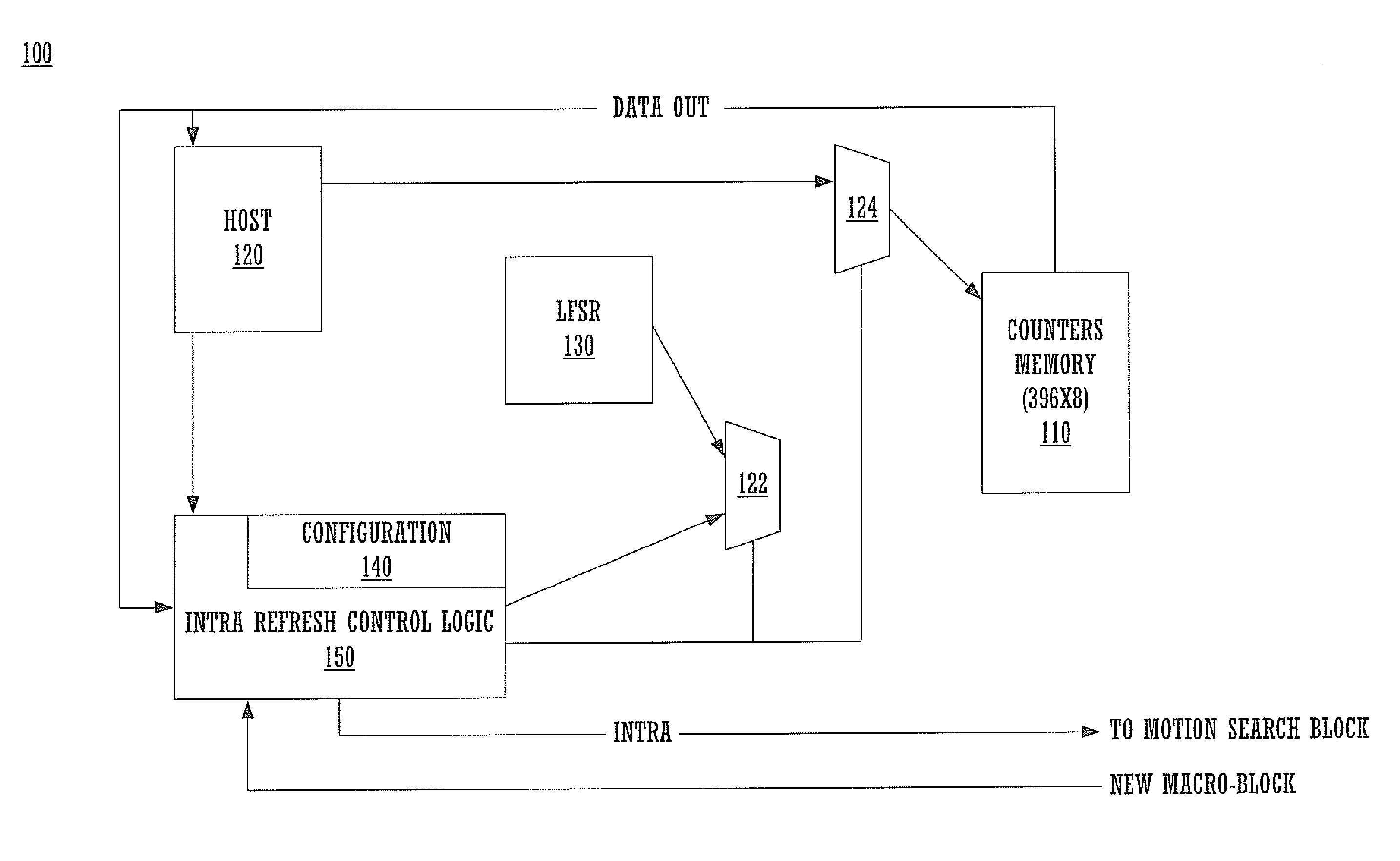
[0011]The value of the counter is used to control the coding type of the macro-block, thus overwriting any of the encoder's own macro-block decision mode. Therefore, by controlling the value of the counter, the driver can control the coding type of each macro-block.
[0014]In one embodiment, the driver may control the value used to initialize and re-initialize the counter on a macro-block per macro-block basis. To simplify the memory access as well as to minimize the interaction between the encoder and the driver, two modes to initialize and re-initialize the macro-block counters may be used. In a random mode, the interaction between the encoder and the driver is reduced. The driver chooses a range, which may be specified by minimum and maximum values. The encoder then generates a pseudo random value that falls in the range specified by the driver, and uses this pseudo-random value to initialize the macro-block counter. A different pseudo random value is generated for each counter. The process may be repeated each time the counter needs to be re-initialized. The range can be on a macro-block-by-macro-block basis, or different ranges can be associated with different Regions of Interest (ROI).

Problems solved by technology

The lack of Intra frames generally results in very poor visual quality.
Sending an Intra frame every 132 times results in a bandwidth spike over the transmission line because the Intra frames are significantly larger than non-Intra frames.
These bandwidth spikes can cause unwanted delays in the rendering of the signal.
This is particularly unwanted for real-time applications, such as video conferencing, etc.

Method used


Image

  • System and method for intra refresh implementation with pseudo random number generation
  • System and method for intra refresh implementation with pseudo random number generation
  • System and method for intra refresh implementation with pseudo random number generation

Examples


Embodiment Construction

[0028]Reference will now be made in detail to the various embodiments of the present invention, examples of which are illustrated in the accompanying drawings. While the invention will be described in conjunction with these embodiments, it will be understood that they are not intended to limit the invention to these embodiments. On the contrary, the invention is intended to cover alternatives, modifications and equivalents, which may be included within the spirit and scope of the invention as defined by the appended claims. Furthermore, in the following detailed description of the present invention, numerous specific details are set forth in order to provide a thorough understanding of the present invention. However, it will be understood that the present invention may be practiced without these specific details. In other instances, well-known methods, procedures, components, and circuits have not been described in detail so as not to unnecessarily obscure aspects of the present inv...


PUM


Abstract

Embodiments of the present invention include a method and system for encoding video data comprising accessing a picture to be encoded, wherein the picture comprises a plurality of macro-blocks. A plurality of programmable counters is associated with each macro-block to be encoded. A counter associated with a macro-block of the plurality of macro-blocks is accessed and a value of the counter is determined. The method further includes determining whether to encode the macro-block as an Intra or non-Intra based on the value of the counter. If the macro-block is encoded as Intra, its counter is reset. If the macro-block is encoded as non-Intra, its counter value is updated. The counter value may be reset with a random number. Counters can be programmed such that a region of interest is defined for updating associated macro-blocks with greater frequency.

Description

CROSS-REFERENCES TO RELATED APPLICATIONS[0001]This Divisional application claims the benefit of the commonly-owned U.S. Patent Application with Attorney Docket No. NVID-P001164, application Ser. No. 11 / 008,324, filed on Dec. 8, 2004, by Moccagatta, et al., and similarly titled “System and Method for Intra Refresh Implementation.”FIELD OF THE INVENTION[0002]The present invention is related to video encoding of digital signals. More particularly, embodiments of the present invention are directed towards video encoding techniques for better bandwidth utilization between a transmitter and a receiver device.BACKGROUND ART[0003]The MPEG (Motion Picture Experts Group) 1 / 2 / 4 and H.261 / 263 video coding standards require each macro-block to be coded as Intra after it has been coded as non-Intra for 132 times consecutively. This requirement reduces the propagation of visual artifacts generated by the IDCT (Inverse Discrete Cosine Transform) mismatch between the encoder and the decoder.[0004]Lo...

Claims


Application Information

Patent Timeline
IPC IPC(8): H04N7/32
CPCH04N19/176H04N19/61H04N19/17H04N19/136H04N19/107
Inventor MOCCAGATTA, IOLEGARG, ATULMONI, SHANKARTALUKDAR, DIPANKARTJANDRASUWITA, IGNATIUS B.SHYAMSUKHA, SANDEEP
Owner NVIDIA CORP
Learn More