
Bioabsorbable stent

a bioabsorbable stent and stent technology, applied in the field of medical devices, can solve the problems of undesirable rapid bioabsorption of bioabsorbable stents, stents being absorbed before the body lumen, and high rates of absorption of stent constituent materials, and achieve the effect of reducing the rate of absorption of the portion

Inactive Publication Date: 2010-05-20
BOSTON SCI SCIMED INC
View PDF24 Cites 24 Cited by
  • Summary
  • Abstract
  • Description
  • Claims
  • Application Information

AI Technical Summary

Benefits of technology

The solution enables a controlled and preselected absorption rate of the stent, ensuring the stent is absorbed before structural support is no longer needed, reducing complications and facilitating subsequent procedures.

Problems solved by technology

Metallic stents can also cause complications, however, such as thrombosis and neointimal hyperplasia.
It is believed that prolonged contact of the metallic surfaces of the stent with the lumen may be a significant factor in these adverse events following implantation.
Although the use of stents formed with magnesium alloys, iron alloys, or biodegradable polymers provides both functional and safety benefits over conventional non-absorbable stents, and the characteristic rate of bioabsorption of the materials used in such stents can lead to other problems.
Rapid bioabsorption of bioabsorbable stents may be undesirable for both health and functional reasons.
For example, rapid bioabsorption of bioabsorbable stents may result in the stent being absorbed before the body lumen has sufficiently healed and become self-supporting.
Further, high rates of absorption of the stents' constituent materials may have undesirable physiological effects.
Conversely, if the stent is absorbed too slowly, it may interfere with a subsequent stenting procedure.

Method used


Image

  • Bioabsorbable stent
  • Bioabsorbable stent
  • Bioabsorbable stent

Examples


Embodiment Construction

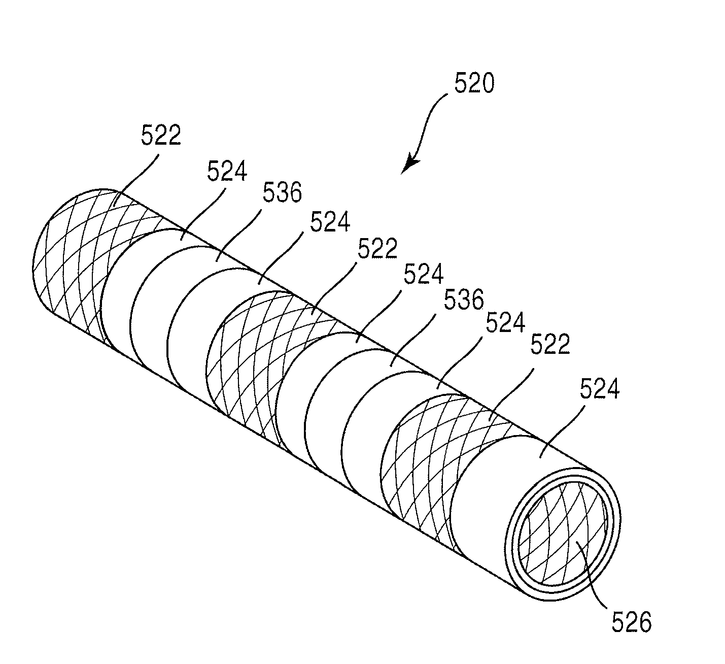
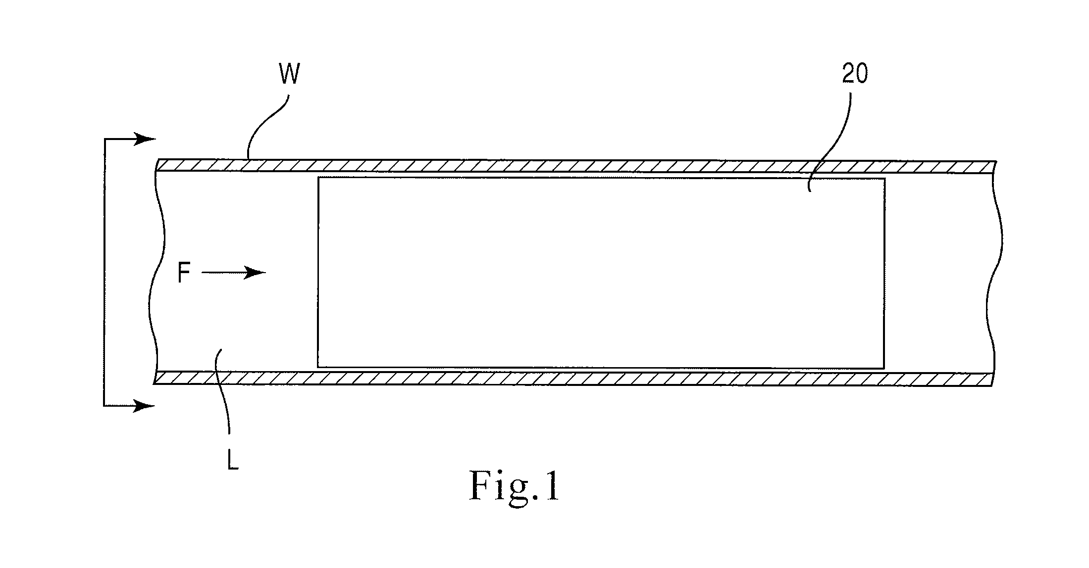
[0021]FIG. 1 is a schematic illustration of a stent 20 embodying the principles of the invention. The stent 20 is configured to be placed or otherwise implanted into a natural body lumen L of a mammal (e.g., a blood vessel or ureter) to support the walls W of the body lumen L, such as after a medical procedure (e.g., a coronary angioplasty). A bodily fluid F may flow through lumen L. The stent 20 is constructed of materials that are configured to be absorbed by the mammalian body over a controlled or predetermined period of time.

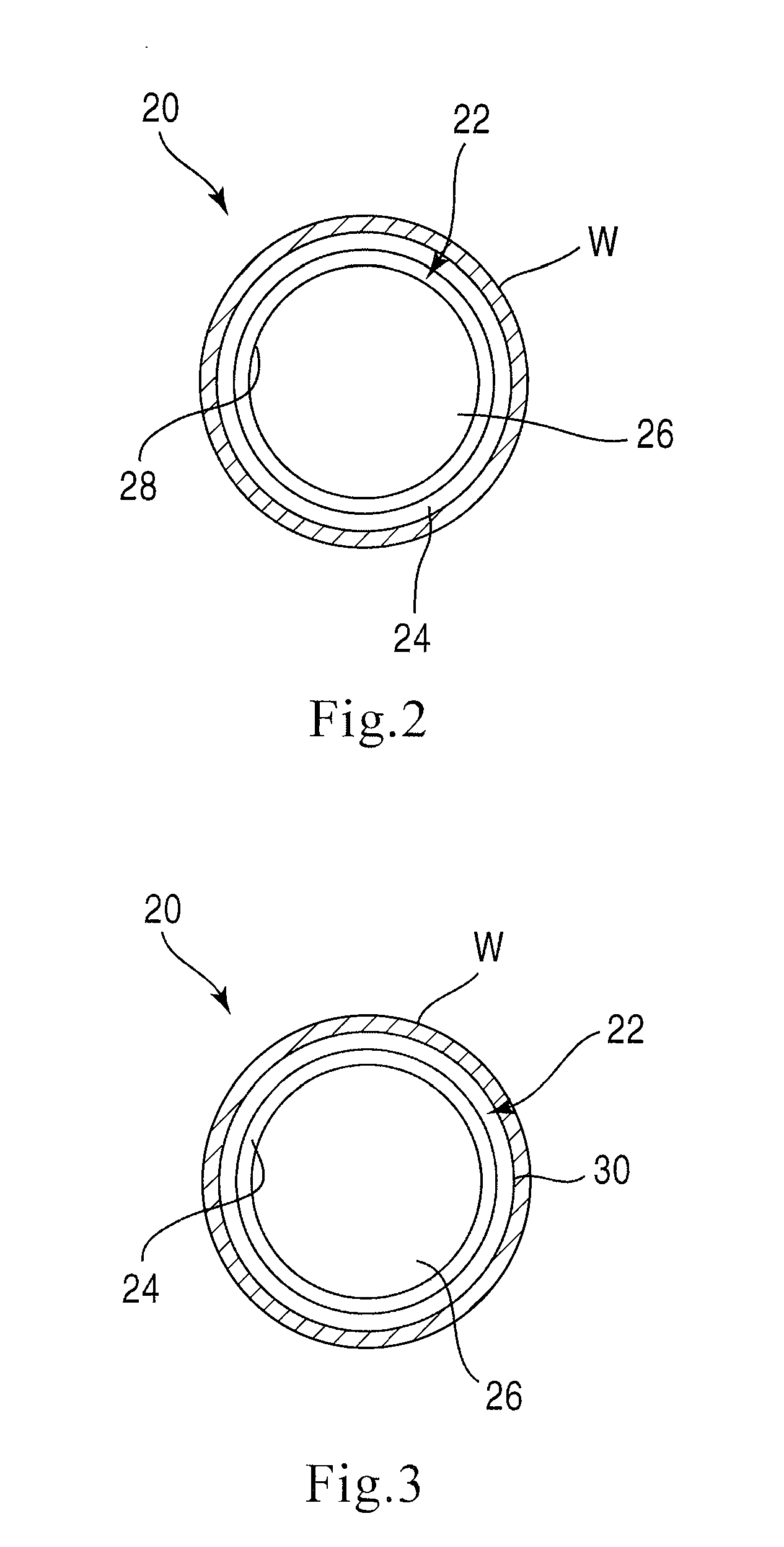
[0022]Specifically, the stent 20 includes a support structure 22 and an absorption inhibitor layer 24. FIGS. 2 and 3 illustrate two alternative cross-sections of the stent 20 shown in FIG. 1. The support structure 22 includes an inner surface 28 and an outer surface 30, and defines a lumen 26. FIG. 2 illustrates stent 20 having an absorption inhibitor layer 24 disposed on the outer surface 30 of stent 20. FIG. 3 illustrates stent 20 having an absorption inhi...


PUM

PropertyMeasurementUnit
thicknessaaaaaaaaaa
lengthaaaaaaaaaa
permeableaaaaaaaaaa

Abstract

A medical device includes a support structure formed of a metal that is absorbable by a mammalian body. A polymer is disposed on the support structure in at least partially overlying relationship. The polymer has a thickness and a rate of absorption by a mammalian body such that said polymer is substantially completely absorbed, exposing the underlying portion of the support structure, before the underlying portion of the support structure is absorbed. In another embodiment, the medical device includes a support structure formed of a first material, the first material being absorbable by a mammalian body. An absorption inhibitor disposed on the support structure in at least partially overlying relationship and formed of a second material different from the first material. The second material being absorbable by the mammalian body The absorption inhibitor reducing a rate of absorption of the portion of the support structure.

Description

RELATED APPLICATIONS[0001]This is a continuation application and claims the benefit of priority of co-pending U.S. patent application Ser. No. 11 / 213,817, filed Aug. 30, 2005, the entire specification of which is incorporated by reference herein.BACKGROUND[0002]The disclosed invention relates generally to a medical device and more particularly to a bioabsorbable stent[0003]Intraluminal stents are typically inserted or implanted into a body lumen, for example, a coronary artery, after a procedure such as percutaneous transluminal coronary angioplasty. Such stents are used to maintain the patency of a body lumen by supporting the walls of the lumen and preventing abrupt reclosure or collapse thereof. These stents can also be provided with one or more therapeutic agents adapted to be locally released from the stent at the site of implantation. In the case of a coronary stent, the stent can be adapted to provide release of, for example, an antithrombotic agent to inhibit clotting or an ...

Claims


Application Information

Patent Timeline
Patent Type & Authority Applications(United States)
IPC IPC(8): A61F2/82
CPCA61F2/82A61F2210/0004A61F2250/003A61L31/148A61L31/022A61L31/10A61F2250/0067
Inventor FLANAGAN, AIDEN
Owner BOSTON SCI SCIMED INC
Learn More