
Hermetic compressor and refrigeration cycle device having the same

Active Publication Date: 2010-05-20
LG ELECTRONICS INC
View PDF5 Cites 29 Cited by
  • Summary
  • Abstract
  • Description
  • Claims
  • Application Information

AI Technical Summary

Benefits of technology

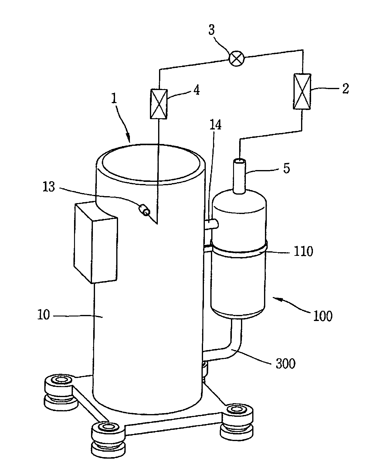
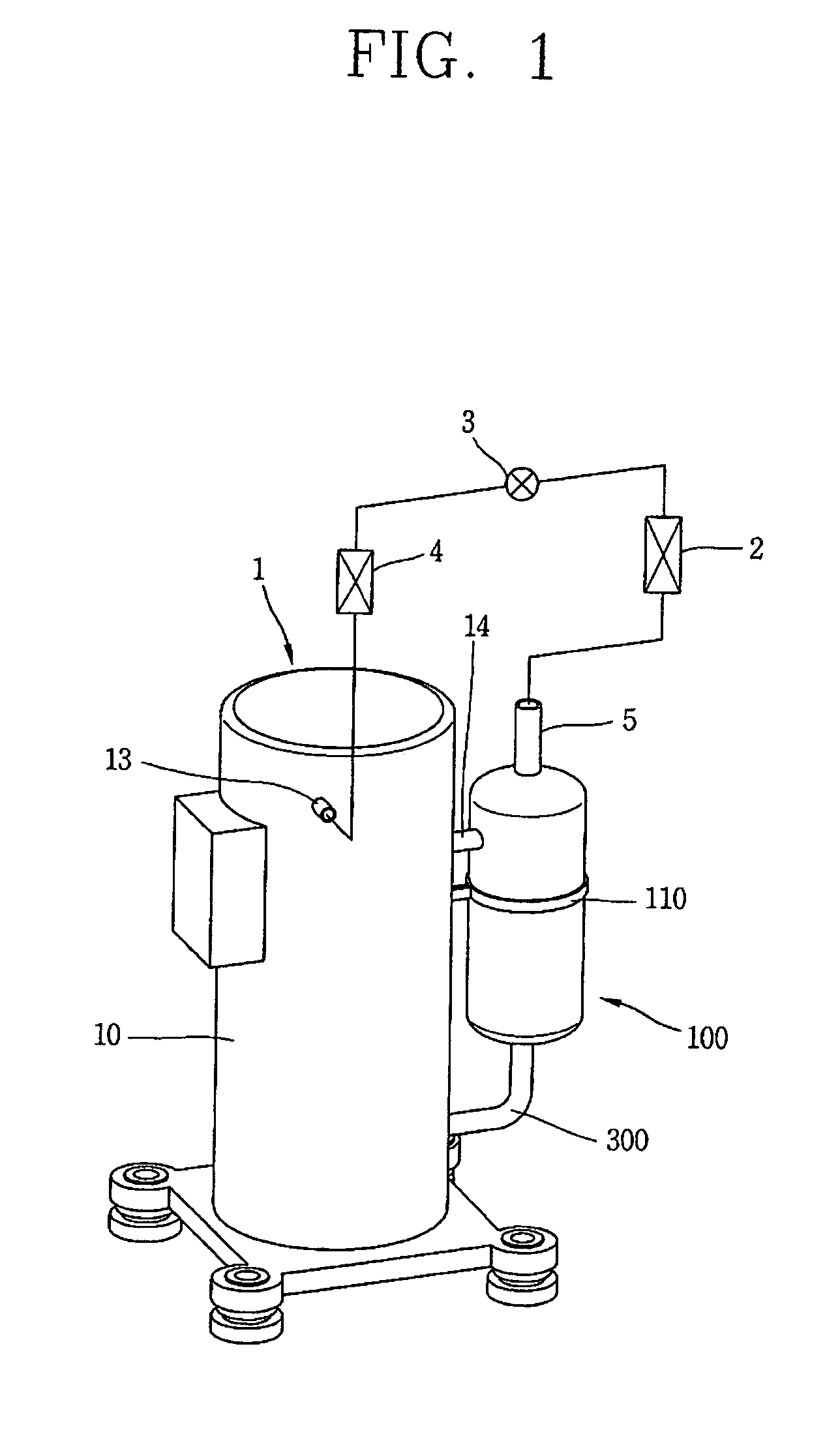
[0011]Therefore, a feature of the invention is a provision of a hermetic compressor capable of preventing temperature increase of a refrigerant discharged from the compressor and sucked to the hermetic compressor due to oil separated from the refrigerant, and capable of forcibly recollecting the oil separated from the refrigerant into the compressor, and a refrigeration cycle device having the same.
[0012]Another feature of the invention is a provision of a hermetic compressor capable of preventing oil recollected into the hermetic compressor after being separated from a refrigerant discharged from the compressor, from being discharged out in a mixed state with a refrigerant sucked into the compressor, and a refrigeration cycle device having the same.
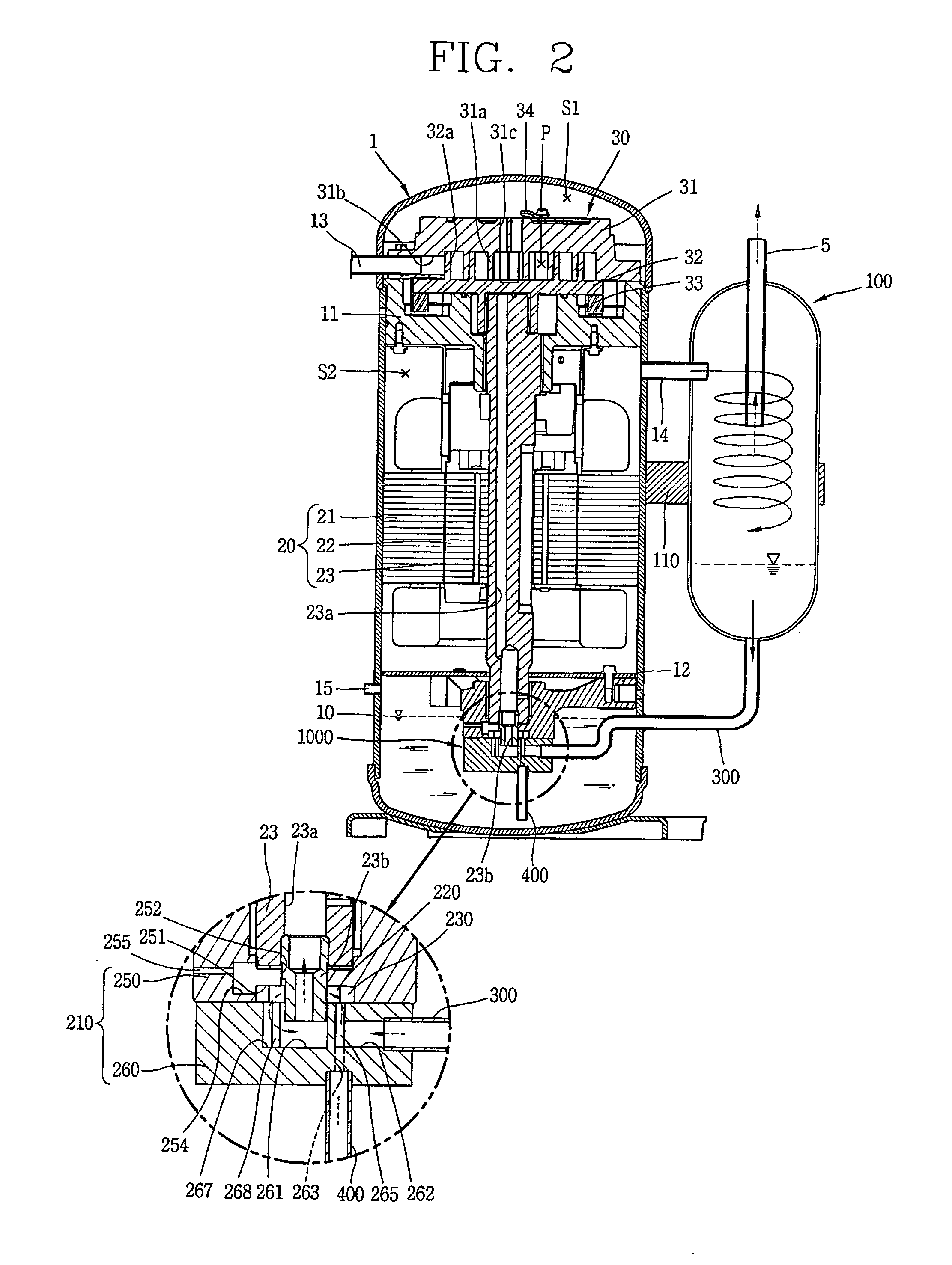
[0014]According to another aspect of the present invention, there is provided a hermetic compressor, comprising: a casing configured to store oil in an inner space of the casing; a driving motor installed within the inner space of the casing; a compression unit installed within the inner space of the casing and configured to compress a refrigerant when driven by the driving motor; an oil separator in fluid communication with an outlet of the compressor and configured to separate oil from the compressed refrigerant discharged from the compression unit; a first oil pump in fluid communication with the oil separator and configured to pump oil separated by the oil separator into the inner space of the casing; a second oil pump in fluid communication with the inner space of the casing and configured to pump oil from the inner space of the casing; a crankshaft coupled to the driving motor, the compression unit, the first oil pump, and the second oil pump, and configured to transmit a driving force of the driving motor to the compression unit, the first oil pump, and the second oil pump, wherein the second oil pump pumps oil to bearing surfaces of the crankshaft and the compression unit; and a backflow preventing portion formed at a housing which accommodates the first oil pump, for preventing oil from back-flowing to the oil separator.

Problems solved by technology

And, some of the oil discharged to the refrigeration cycle may remain in the refrigeration cycle without being recollected into the hermetic compressor, resulting in oil deficiency inside the hermetic compressor.
This may lower reliability of the hermetic compressor, and the refrigeration cycle may have a lowered heat exchange performance due to the oil remaining therein.
First, because an outlet of the conventional oil separator is connected to the inlet of the compressor having a relatively low pressure, not only the oil separated by the oil separator but also the refrigerant may backflow to the inlet of the compressor. This may cause the amount of the refrigerant which circulates in the refrigeration cycle to be deficient, thereby resulting in a low cooling capability of the refrigeration cycle.
Second, because high-temperature oil and refrigerant are sucked to the inlet of the compressor, a suction refrigerant has an increased temperature. This may increase a volume ratio of the refrigerant, and thus the amount of the refrigerant sucked to the compression unit of the compressor is reduced. This may result in a lowered cooling capability of the compressor.
Third, because the oil separated by the oil separator is mixed with a sucked refrigerant thus to be discharged from the compression unit, oil deficiency may occur within the inner space of the casing. This may lower the reliability of the compressor.

Method used


Image

  • Hermetic compressor and refrigeration cycle device having the same
  • Hermetic compressor and refrigeration cycle device having the same
  • Hermetic compressor and refrigeration cycle device having the same

Examples


second embodiment

[0061]Hereinafter, an oil pump according to another embodiment of the present invention will be described. In the aforementioned embodiment, one oil pump 1000 was used to both recollect oil separated from a refrigerant by the oil separator 100 and to pump oil stored within the inner space of the casing into the oil passage 23a of the crankshaft 23. However, in the second embodiment, a plurality of oil pumps 1200, 1300 are provided.

first embodiment

[0062]In the embodiment of FIG. 9, a first oil pump 1200 is configured to recollect oil from the oil separator 100, whereas a second oil pump 1300 is configured to pump oil stored within the inner space of the casing 10 into the oil passage 23a of the crankshaft 23. For this, the first oil pump 1200 and the second oil pump 1300 may be implemented as trochoid gear pumps having first and second variable capacities, similar to the oil pump 1000 of the As illustrated in the embodiment of FIG. 9, the first oil pump 1200 and the second oil pump 1300 may be arranged at upper and lower sides of each other in an axial direction, e.g., along the axis of rotation of the two pumps.

[0063]As illustrated in FIG. 9, at a bottom surface of an upper housing 1111, formed is a first pumping space 1151 for inserting a first inner gear 1210 and a first outer gear 1220. At an upper surface of the upper housing 1111, formed is a shaft groove 1152 for inserting the crankshaft 23. Between the shaft groove 1...


PUM


Abstract

To a hermetic compressor and a refrigeration cycle device having the same, an oil separator for separating oil from a refrigerant discharged from a compression unit is added. Separated oil is recollected into an oil pump driven by a driving motor. Because refrigerant separated from the oil is prevented from being re-introduced into the compressor, a cooling capability of the refrigeration cycle device may be enhanced. Because the oil pump is driven by the driving force of the driving motor, the compressor may have a simplified configuration, and the fabrication costs may be reduced. The oil used for a crankshaft lubrication process is returned to the oil pump by forming an oil pocket between bearing surfaces of a crankshaft and the oil pump, oil may be prevented from back-flowing to the oil separator from the crankshaft. This may allow oil to be smoothly recollected into the oil pump.

Description

[0001]This application claims priority to Korean Patent Application No. 10-2008-0113667, filed on Nov. 14, 2008 in the Republic of Korea, the contents of which is hereby incorporated by reference in its entirety.BACKGROUND OF THE INVENTION[0002]1. Field of the Invention[0003]The present invention relates to a hermetic compressor and a refrigeration cycle device having the same, and particularly, to a hermetic compressor capable of separating oil from a refrigerant discharged from a compression unit and recollecting the oil to the hermetic compressor, and a refrigeration cycle device having the same.[0004]2. Background of the Invention[0005]A compressor is an apparatus for converting mechanical energy into fluid compression energy. A hermetic compressor is provided with a driving motor for generating a driving force, and a compression unit for compressing fluid by receiving the driving force of the driving motor. The driving motor and the compression unit are installed in an inner sp...

Claims


Application Information

Patent Timeline
IPC IPC(8): F25B43/02F25B39/04F04B39/02F04B39/06
CPCF01C21/007F04C23/008F04C2240/809F04C29/025F04C29/028F04C29/023F04C29/02F04C18/02
Inventor CHO, NAM-KYUPARK, HYO-KEUNLEE, BYEONG-CHULCHOI, SE-HEON
Owner LG ELECTRONICS INC
Learn More