
Adaptive frequency domain equalization without cyclic prefixes

Inactive Publication Date: 2010-05-13
NEC LAB AMERICA
View PDF5 Cites 30 Cited by
  • Summary
  • Abstract
  • Description
  • Claims
  • Application Information

AI Technical Summary

Problems solved by technology

Most installed Ethernet backbones, based on multi-mode fibers, operate at bit rate of roughly 1 Gb / s, which is inadequate for current and emerging demands.
CD is usually a much larger impairment than PMD, and can be a significant distortion even at relatively low data rates on long fibers.
Difficulties arise when the resulting energy from a pulse begins to interfere with that of an adjacent pulse.
This interference causes inter-symbol interference in the electrical domain.
However, such passive devices have drawbacks, in that they substantially reduce the optical signal-to-noise ratio.
PMD, meanwhile, is an effect based in the defects of the transmission medium and cannot be compensated for passively.
In real media, however, defects cause random differences in the speeds of the respective polarizations, causing the polarizations to drift with respect to one another.
The dynamic characteristic of PMD makes it a difficult problem for high-speed optical transmissions.
However, the complexity of the time-domain signal processing methods increase quickly with the channel delay spread.
Consequently, time-domain methods are difficult to implement for high-speed long-distance fiber systems, where the dispersion may span several hundreds of symbol durations.
However, because polarization dispersion can change rapidly with time, the speed of optical PMD compensation is often not enough to compensate for the fastest polarization changes that can occur.
However, adding a DCF gives rise to a reduction of the receiving optical signal-to-noise ratio (SNR) and thereby degrades the performance of the system.
However, as noted above, the channel delay spread for high-speed, long-distance fiber systems may span several hundred symbol durations.
Because the complexity increases with the square of the number of taps, even the conceptually simple linear equalization method can be very difficult to implement in real-time, due to its high computational complexity.
However, in the prior art techniques, a cyclic prefix must to be appended to the end of each data frame, which brings about extra overhead and also increases the complexity of implementation.
Compensation for CD that relies on foreknowledge of the dispersive effects of the particular channel it is being used with cannot account for the dynamic errors introduced by PMD.

Method used


Image

  • Adaptive frequency domain equalization without cyclic prefixes
  • Adaptive frequency domain equalization without cyclic prefixes
  • Adaptive frequency domain equalization without cyclic prefixes

Examples


Embodiment Construction

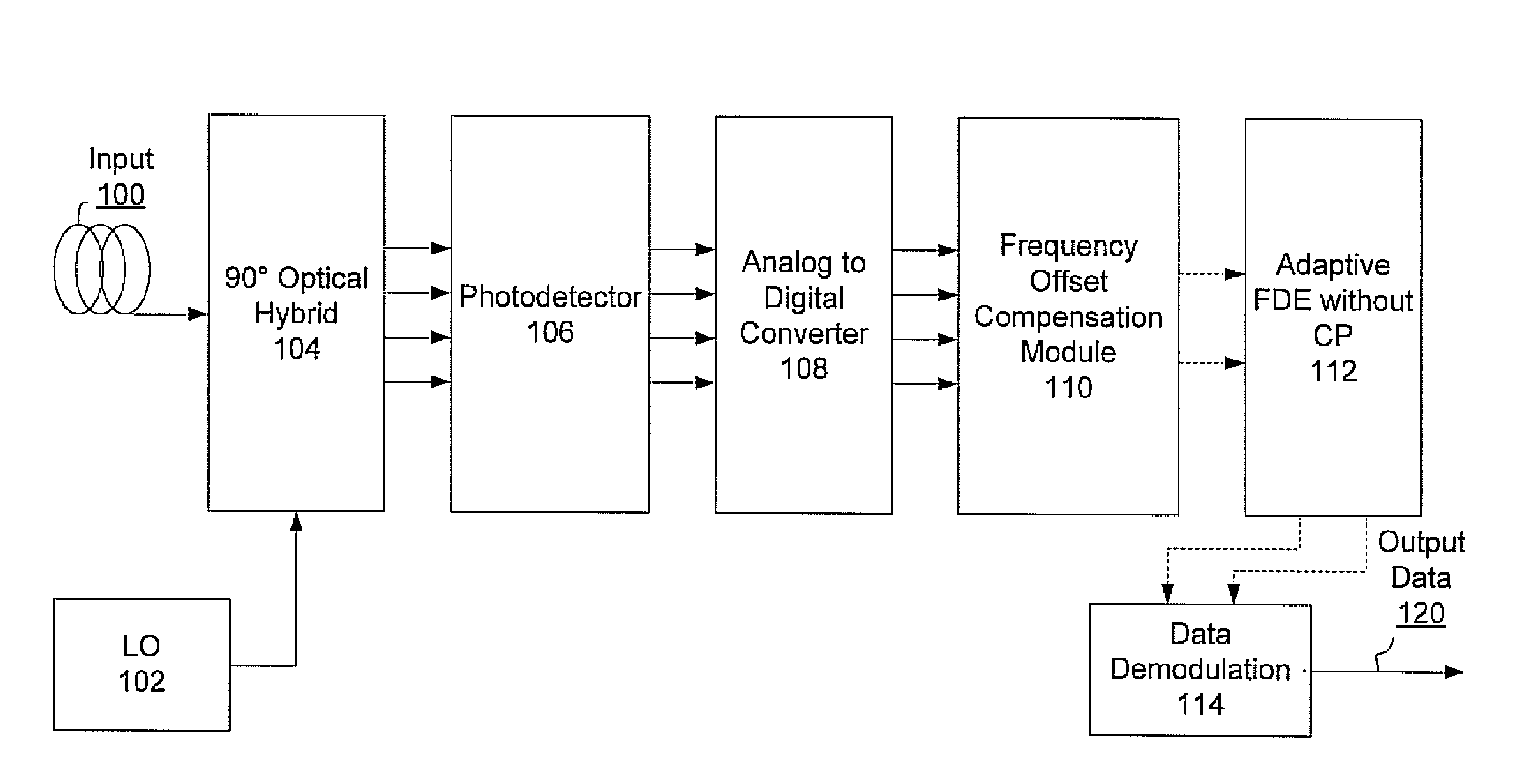
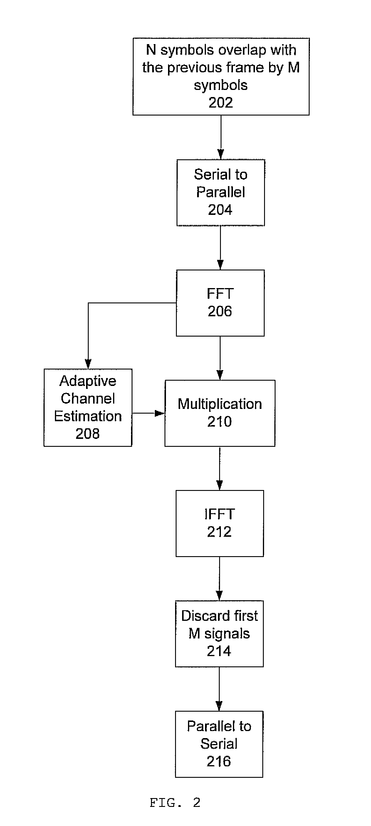
[0022]According to the present principles, it is possible to simultaneously compensate for chromatic dispersion (CD) and polarization mode dispersion (PMD) in the frequency domain without the use of a cyclic prefix.

[0023]Embodiments described herein may be entirely hardware, entirely software or including both hardware and software elements. In a preferred embodiment, the present invention is implemented in software, which includes but is not limited to firmware, resident software, microcode, etc.

[0024]Embodiments may include a computer program product accessible from a computer-usable or computer-readable medium providing program code for use by or in connection with a computer or any instruction execution system. A computer-usable or computer readable medium may include any apparatus that stores, communicates, propagates, or transports the program for use by or in connection with the instruction execution system, apparatus, or device. The medium can be a magnetic, optical, electro...


PUM


Abstract

Polarization multiplexing, optical communications systems can suffer from chromatic dispersion and polarization mode dispersion, resulting in channel delay spread. These errors can be compensated quickly and simply in the frequency domain. By obviating the need for a cyclic prefix, the complexity of the equalization can be reduced by more than a factor of twenty.

Description

RELATED APPLICATION INFORMATION[0001]This application claims priority to provisional application Ser. No. 61 / 112,938 filed on Nov. 10, 2008, incorporated herein by reference.BACKGROUND[0002]1. Technical Field[0003]The present invention relates to optical communications systems, and more particularly to an apparatus and a method for compensating for chromatic dispersion and polarization-mode dispersion in a coherent, polarization multiplexing receiver.[0004]2. Description of the Related Art[0005]Most installed Ethernet backbones, based on multi-mode fibers, operate at bit rate of roughly 1 Gb / s, which is inadequate for current and emerging demands. Recently, polarization multiplexing (PolMux) systems with coherent detection schemes have received significant research interests for high-speed (40 Gb / s and beyond) transmissions. Unlike the conventional systems, PolMux system with coherence detection could utilize advanced signal processing technologies to mitigate optical-channel distor...

Claims


Application Information

Patent Timeline
IPC IPC(8): H04B10/06
CPCH04B10/60H04B10/611H04B10/6971H04B10/6162H04B10/6161H04B10/65
Inventor YANG, KAIWANG, TING
Owner NEC LAB AMERICA
Learn More