
Optical receiver having a signal-equalization capability

Active Publication Date: 2014-03-27
ALCATEL LUCENT SAS
View PDF8 Cites 28 Cited by
  • Summary
  • Abstract
  • Description
  • Claims
  • Application Information

AI Technical Summary

Benefits of technology

The patent describes an optical receiver that uses a bulk dispersion compensator and a butterfly equalizer to process optical signals. The bulk compensator has a larger capacity but is slower and works in a static way, while the butterfly equalizer has a smaller capacity but can change quickly to adapt to changing conditions. The receiver also has a feedback path that allows the compensator to change based on the equalizer's configuration, which makes the receiver better able to handle larger amounts of dispersion. Overall, the invention improves the receiver's ability to handle complex optical signals.

Problems solved by technology

At these rates, the effects of chromatic dispersion (CD) and polarization-mode dispersion (PMD) can significantly degrade the transmission performance of optical-transport links.

Method used


Image

  • Optical receiver having a signal-equalization capability
  • Optical receiver having a signal-equalization capability
  • Optical receiver having a signal-equalization capability

Examples


Embodiment Construction

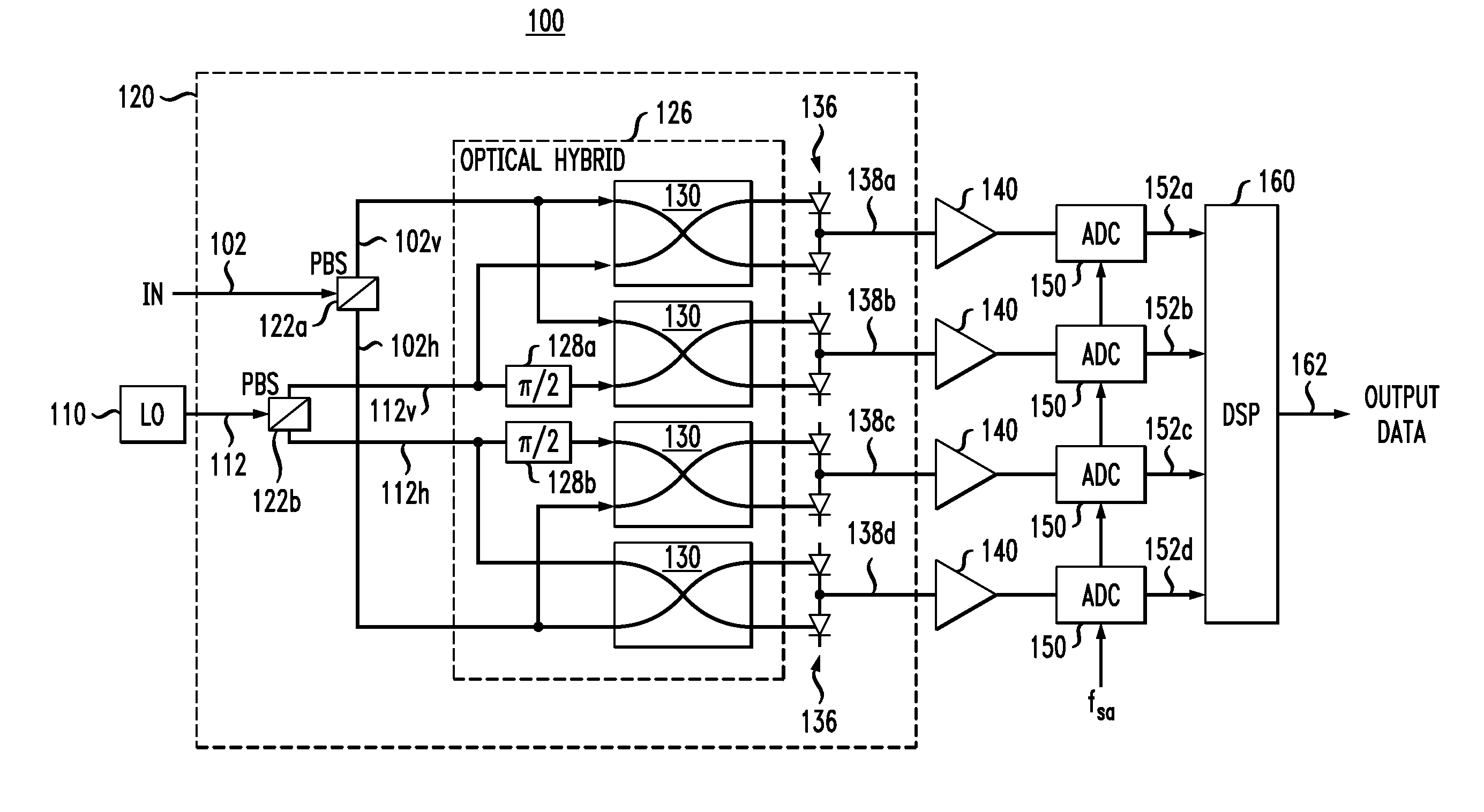
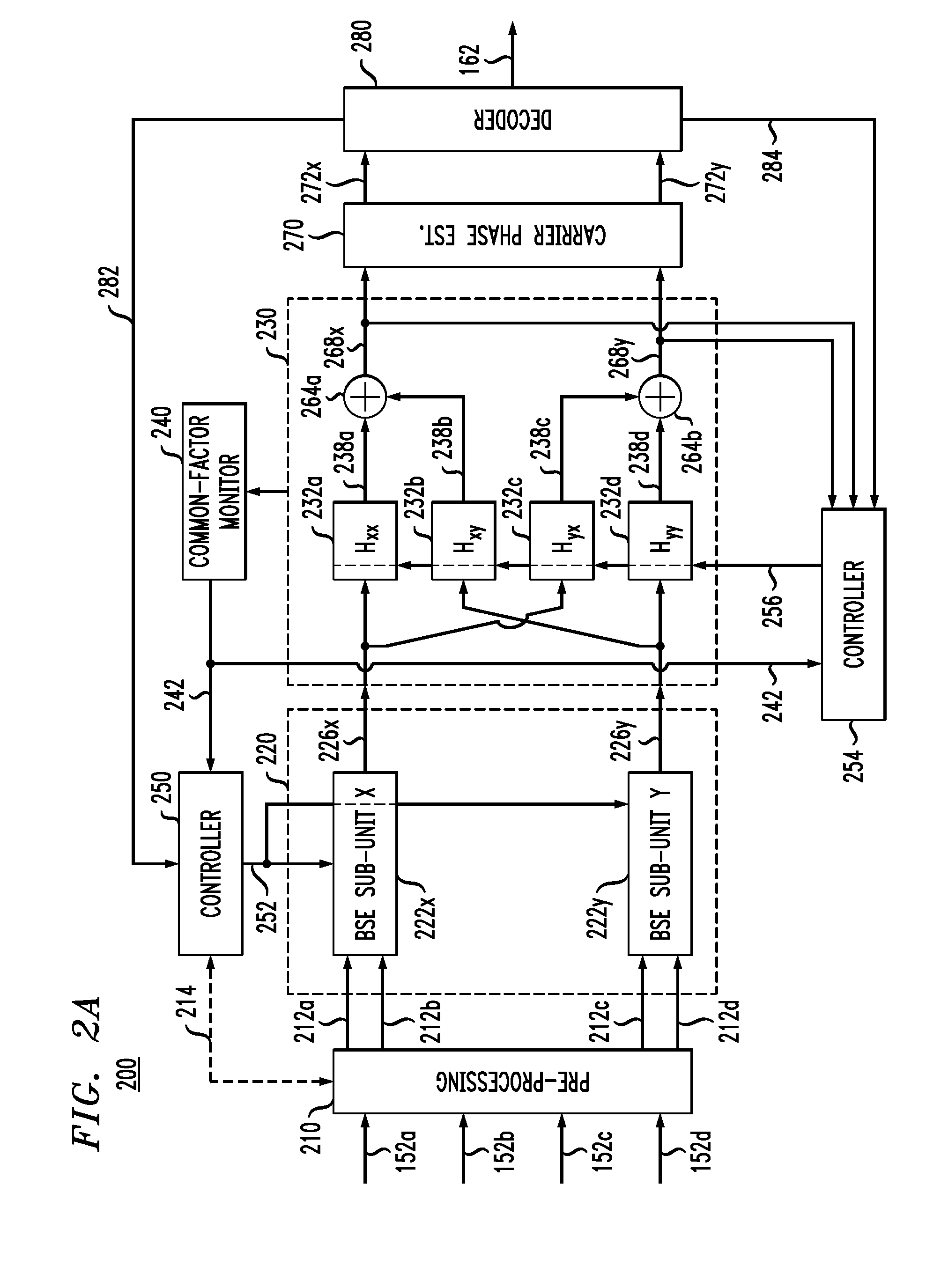
[0006]Disclosed herein is an optical receiver that, in one embodiment, has a bulk dispersion compensator and a butterfly equalizer serially connected to one another to perform dispersion-compensation processing and electronic polarization de-multiplexing. The bulk dispersion compensator has a relatively large dispersion-compensation capacity, but is relatively slow and operates in a quasi-static configuration. The butterfly equalizer has a relatively small dispersion-compensation capacity, but can be dynamically reconfigured on a relatively fast time scale to track the changing conditions in the optical-transport link. The optical receiver has a feedback path that enables the configuration of the bulk dispersion compensator to be changed based on the configuration of the butterfly equalizer in a manner that advantageously enables the receiver to tolerate larger amounts of chromatic dispersion (CD) and / or polarization-mode dispersion (PMD) than without the use of the feedback path.

[0...


PUM


Abstract

In one embodiment, an optical receiver has a bulk dispersion compensator and a butterfly equalizer serially connected to one another to perform dispersion-compensation processing and electronic polarization de-multiplexing. The bulk dispersion compensator has a relatively large dispersion-compensation capacity, but is relatively slow and operates in a quasi-static configuration. The butterfly equalizer has a relatively small dispersion-compensation capacity, but can be dynamically reconfigured on a relatively fast time scale to track the changing conditions in the optical-transport link. The optical receiver has a feedback path that enables the configuration of the bulk dispersion compensator to be changed based on the configuration of the butterfly equalizer in a manner that advantageously enables the receiver to tolerate larger amounts of chromatic dispersion and / or polarization-mode dispersion than without the use of the feedback path.

Description

BACKGROUND[0001]1. Field[0002]The present disclosure relates to optical communication equipment and, more specifically but not exclusively, to optical receivers having signal-equalization means, such as for mitigating the detrimental effects of chromatic and / or polarization-mode dispersion.[0003]2. Description of the Related Art[0004]This section introduces aspects that may help facilitate a better understanding of the invention(s). Accordingly, the statements of this section are to be read in this light and are not to be understood as admissions about what is in the prior art or what is not in the prior art.[0005]The next-generation of optical communication systems is being designed for relatively high data-transmission rates, e.g., higher than about 100 Gbit / s per channel. At these rates, the effects of chromatic dispersion (CD) and polarization-mode dispersion (PMD) can significantly degrade the transmission performance of optical-transport links. Accordingly, methods for mitigat...

Claims


Application Information

Patent Timeline
IPC IPC(8): H04B10/06
CPCH04B10/6161H04B10/6162H04B10/6165
Inventor XIE, CHONGJINWINZER, PETER J.WEISSER, STEFANLEVEN, ANDREAS
Owner ALCATEL LUCENT SAS
Learn More