Programmable Gain Amplifier and Transconductance Compensation System

a transconductance compensation and gain amplifier technology, applied in the field of programmable amplification, can solve the problems of large variability and unpredictability of the magnitude of the received communication signal, loss of information, and problems, and achieve the effect of minimizing noise, increasing or decreasing the magnitude of the signal

Inactive Publication Date: 2010-05-13
AVAGO TECH INT SALES PTE LTD
View PDF99 Cites 7 Cited by
  • Summary
  • Abstract
  • Description
  • Claims
  • Application Information

AI Technical Summary

Benefits of technology

The invention is a programmable gain amplifier that has separate front and back ends. Each end can be programmed to control different aspects of the amplifier's operation. The front end has transconductors that can be switched in and out to control the gain of the signal. The back end has current-mode gain stages that can be switched in or out to control the amplification of the signal. This separation of control allows for better tradeoffs between signal amplification and noise reduction. The amplifier can be used in a system with a front end and a back end, and the control logic can adjust the ratio between the received voltage and the current. The technical effect of this invention is a more efficient and effective programmable gain amplifier.

Problems solved by technology

As a result, the magnitude of received communication signals may vary widely and unpredictably.
A wide variability in signal magnitude may result in loss of information when the signal is converted to digital values at the analog to digital converter.
Problems arise when the received signal is between, for example, 0 and 2 Volts or 0 and 10 Volts.
In these cases the signal is mismatched to the input range of the analog to digital converter.
One problem in using a series of gain stages is that any noise introduced by the first gain stage is amplified by later stages.
Another problem of using a series of gain stages is to maintain linearity of the system.
These two factors result in a trade-off between linearity and noise for the system.
The elements of each stage may be single-ended or differential, and the amplification may result in an increase or a decrease in the magnitude of the signal.

Method used


Image

  • Programmable Gain Amplifier and Transconductance Compensation System
  • Programmable Gain Amplifier and Transconductance Compensation System
  • Programmable Gain Amplifier and Transconductance Compensation System

Examples


Embodiment Construction

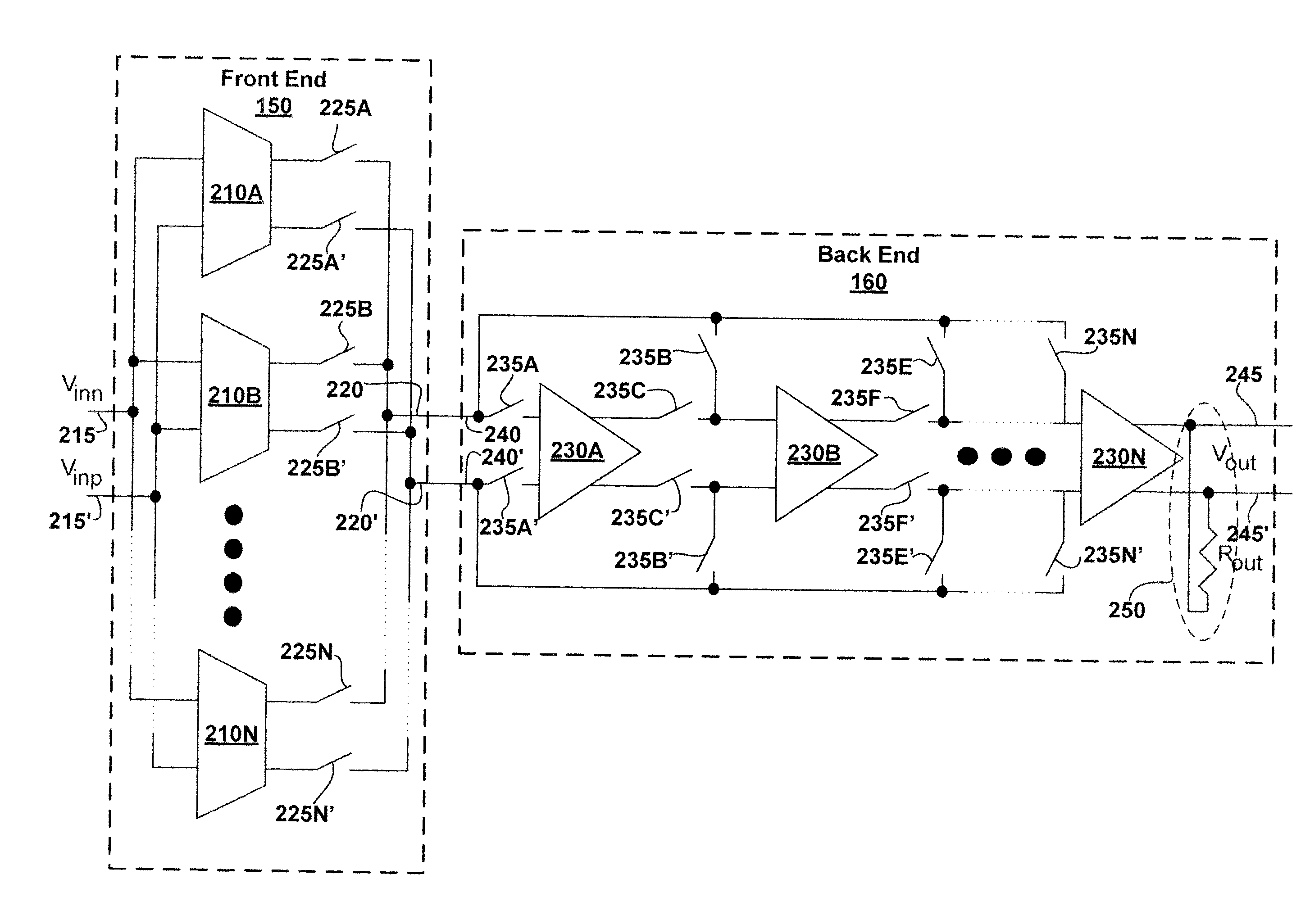
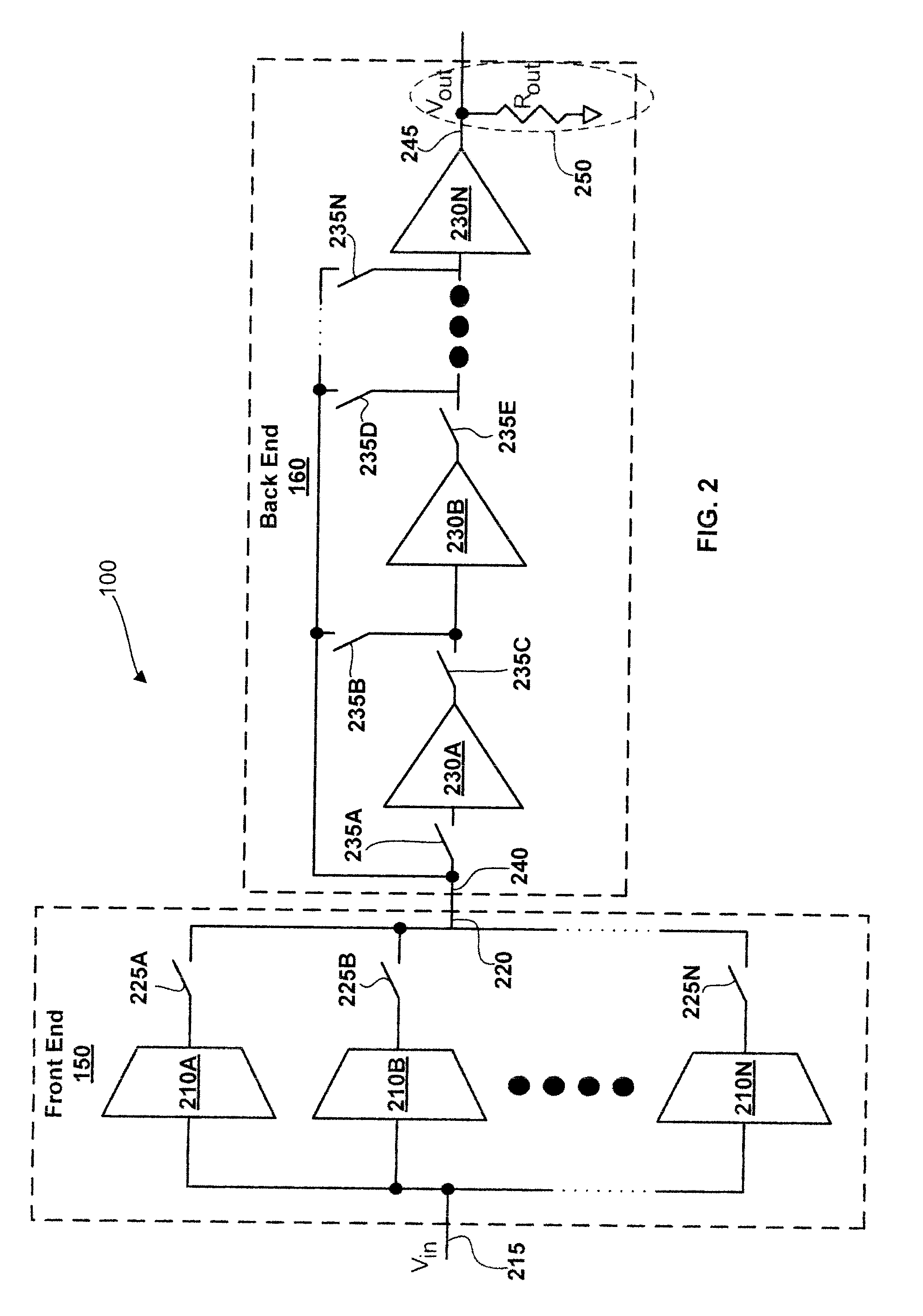
[0034]An improved programmable gain amplifier includes different types of circuits in a front end and a back end. The front end comprises a plurality of transconductors in parallel. Switches are configured to create a signal path selectively through one or more of these transconductors, responsive to the magnitude of a received signal. Each of the transconductors is configured to generate a current proportional to a received signal voltage. The ratio of received voltage to generated current is typically different for each transconductor. Each transconductor may further be configured to receive signals in a different voltage range. For example, one transconductor may be configured to receive signals between 0 and 1 Volts while another of the transconductors is configured to receive signals between 0 and 2 Volts. The plurality of transconductors in the front end allows for the selection and use of a transconductor best configured to receive a particular signal. In various embodiments ...


PUM


Abstract

A programmable gain amplifier (PGA) system comprises selectable parallel transconductors in a front end, independently selectable serial amplification circuits in a back end. The back end is configured to receive an output of the front end and may include a plurality of current or voltage mode amplifiers in series. The PGA system also includes control circuitry to select a gain configuration for the PGA by selecting selectable components in the front and back ends. The PGA system may additionally include control circuitry configured to change the transconductance of one or more of the front end transconductors such that the gain configurations of the PGA are independent of variations such as those due to temperature and fabrication. The PGA system may be used between a signal receiver and an analog to digital converter.

Description

CROSS-REFERENCE TO RELATED APPLICATIONS[0001]This application is a Continuation-in-part of U.S. patent application Ser. No. 12 / 250,450 entitled “Programmable Gain Amplifier” filed Oct. 13, 2008. This application is related to U.S. patent application Ser. No. 11 / 467,141 entitled “Multi-Wideband Communications over Power Lines” filed Sep. 28, 2006; U.S. patent application Ser. No. 12 / 075,888 entitled “Coupling Signal Processing Circuitry with a Wireline Communication Medium” filed Mar. 14, 2008; U.S. patent application Ser. No. 11 / 752,887 entitled “Multi-Wideband Communications over Multiple Mediums” filed May 23, 2007; and U.S. patent application Ser. No. 12 / 145,475 “entitled Resistor-Input Transconductor Including Common-Mode Compensation” filed Jun. 24, 2008 and issued as U.S. Pat. No. 7,602,220 on Oct. 13, 2009. The disclosures of each of the above patent applications are incorporated herein by reference.BACKGROUND[0002]1. Field of the Invention[0003]The invention is in the field ...

Claims


Application Information

Patent Timeline
Patent Type & Authority Applications(United States)
IPC IPC(8): H03F3/45
CPCH03F1/0277H03F3/72H03G1/0088H03F2203/7239H03F2200/405
Inventor HURWITZ, JONATHAN EPHRAIM DAVIDBOFILL-PETIT, ADRIAHENDERSON, ROBERT K.
Owner AVAGO TECH INT SALES PTE LTD
Why Eureka
Try Eureka