Ion trap mass spectrometer

a mass spectrometer and ion trap technology, applied in the field of ion trap mass spectrometers, can solve the problems of low signal-to-noise ratio (s/n) of the mass spectrum data obtained by one mass analysis, elongation of measuring time to obtain a measurement result, i.e. a final mass spectrum, and decrease the throughput of analysis, so as to achieve the effect of improving throughput of analysis, reducing the time required for the creation

Active Publication Date: 2010-05-13
SHIMADZU CORP
View PDF5 Cites 37 Cited by
  • Summary
  • Abstract
  • Description
  • Claims
  • Application Information

AI Technical Summary

Benefits of technology

[0050]In the ion trap mass spectrometer according to the present invention, while ions are captured in the ion trap, ions newly generated can further be added and injected into the ion trap. Therefore, the mass separation and detection can be performed after the amount of the ions captured in the ion trap is increased, and the target ion can be detected with higher signal intensity than before. Hence, a mass spectrum with a sufficiently high S / N can be created without repeating the mass analysis and summing up the results, or with less number of repetitions of such mass analysis and summation. In addition, the measuring time required for the creation of a mass spectrum with a comparable S / N can be significantly reduced than before. Hence, the throughput of an analysis can be improved and simultaneously the cost required for an analysis of one sample can be reduced.
[0051]In the embodiment in which the ion trap mass spectrometer according to the present invention is used for a mass calibration, the mass accuracy as high as the internal reference method can be achieved, while avoiding the troubles of sample preparation for a general internal reference method and the problems in ion generation. In addition, a mass calibration substantially as accurate as the internal reference method can be performed not only in a general mass analysis, but also in an MS / MS analysis or MSn analysis.

Problems solved by technology

However, in a general MALDI, one pulse of laser light irradiation often fails to generate a sufficient amount of ions, and in such a case, the signal-to-noise ratio (S / N) of the mass spectrum data obtained by one mass analysis as described above is low.
However, this causes a problem in that the measuring time to obtain a measurement result, i.e. a final mass spectrum, is elongated.
Therefore, about 11 seconds are required for a total of ten times, and about 33 seconds for a total of thirty times. Accordingly, the throughput of analysis decreases and the cost of analysis increases.

Method used


Image

  • Ion trap mass spectrometer
  • Ion trap mass spectrometer
  • Ion trap mass spectrometer

Examples


first embodiment

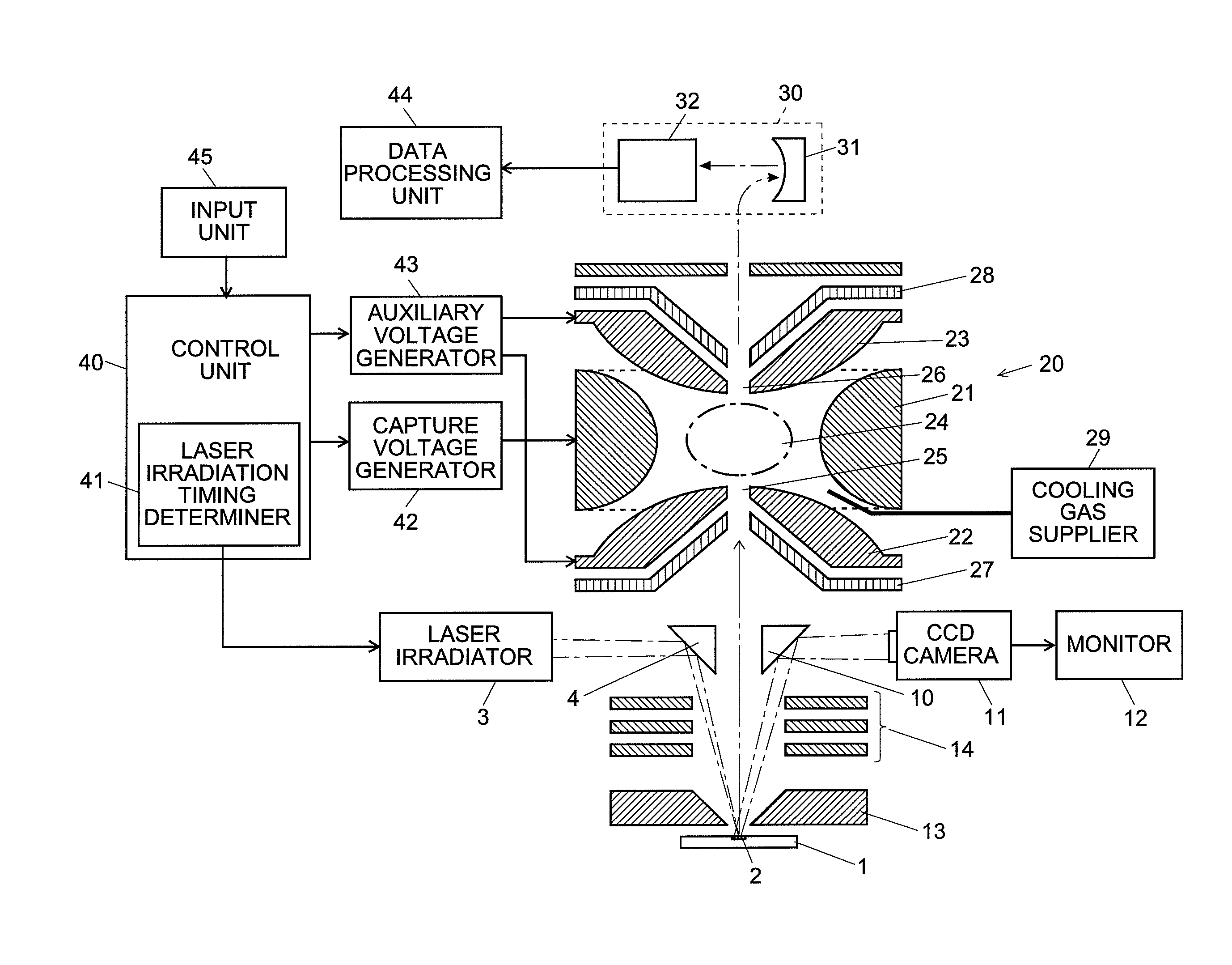
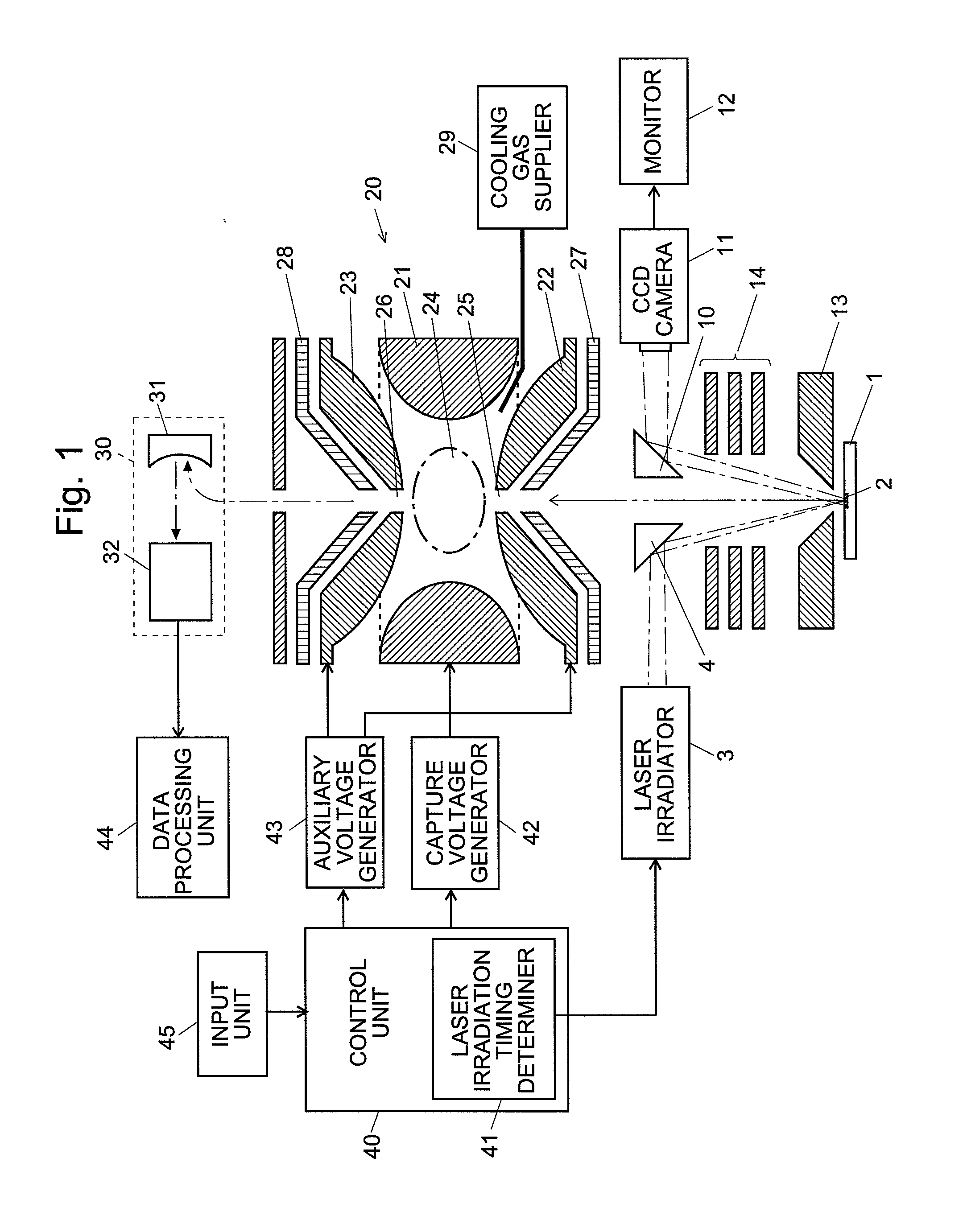
[0091]The configuration and operation of the matrix assisted laser desorption ionization digital ion trap mass spectrometer (MALDI-DIT-MS) which is an embodiment (the first embodiment) of the present invention will be described in detail. FIG. 1 is an entire configuration diagram of the MALDI-DIT-MS according to this embodiment.

[0092]The ion trap 20 is the three-dimensional quadrupole ion trap which is composed of a circular ring electrode 21 and a pair of end cap electrodes 22 and 23 opposing each other (high and low in FIG. 1) with the ring electrode 21 therebetween. The inner surface of the ring electrode 21 has the shape of a hyperboloid-of-one-sheet-of-revolution, and that of the end cap electrodes 22 and 23 has the shape of a hyperboloid-of-two-sheets-of-revolution. The space surrounded by the ring electrode 21 and the end cap electrodes 22 and 23 forms a capture region 24. An ion inlet 25 is bored through the substantially center of the entrance-side end cap electrode 22. Out...

second embodiment

[0127]Next, as another embodiment (the second embodiment) of the present invention, a MALDI-DIT-MS in which the function of the additional ion injection into the ion trap as previously described is used for a mass calibration will be described. Generally, in order to obtain data with high mass accuracy in a mass spectrometer, it is inevitable to perform a mass calibration using a standard sample whose mass is known. A mass calibration in a conventional MALDI-IT-MS is performed in the same manner as an apparatus without an ion trap such as a MALDI-TOFMS. Generally, there are two methods for performing a mass calibration in a MALDI-TOFMS: the external standard method and the internal standard method.

[0128]In performing a mass calibration by the external standard method, before a measurement of an analysis sample (analyte), an analysis operator applies a calibration sample (calibrant) including a compound whose mass is known at a different position on a sample plate from the analysis s...


PUM


Abstract

While applying a square wave voltage to the ion electrode (21) so that ions already captured in the ion trap (20) do not disperse, the timing of irradiating a laser light for ion generation is controlled in such a manner that ions reach the ion inlet (25) at a predetermined timing of a cycle of the voltage. In the case of a positive ion (cation) for example, the timing of laser light irradiation is adjusted in such a manner that the target ions reach the ion inlet (25) in the low level period of a cycle of the square wave voltage. By injecting ions in addition to the ions already captured in the ion trap (20) in this manner, the amount of ions can be increased, and by performing a mass separation and detection after that, the signal intensity in one mass analysis can be increased. Accordingly, by decreasing the number of repetitions of the mass analysis for summing up mass profiles, the measuring time can be shortened.

Description

TECHNICAL FIELD[0001]The present invention pertains to an ion trap mass spectrometer having an ion trap for trapping ions by an electric field.BACKGROUND ART[0002]One conventionally known type of mass spectrometer uses an ion trap for capturing (or trapping) ions by an electric field. A typical ion trap is a so-called three-dimensional quadrupole ion trap, which has a substantially-circular ring electrode and a pair of end cap electrodes placed in such a manner as to face each other across the ring electrode. In such an ion trap, conventionally, a sinusoidal radio-frequency voltage is applied to the ring electrode to form a capture electric field, and ions are oscillated and trapped by this capture electric field. In recent years, the digital ion trap (DIT) for trapping ions by applying a square wave wave voltage in place of a sinusoidal voltage has been developed (refer to Non-Patent Document 1 and other documents).[0003]In the case where the sample is biological, a laser desorptio...

Claims


Application Information

Patent Timeline
Patent Type & Authority Applications(United States)
IPC IPC(8): H01J49/34
CPCH01J49/164H01J49/424H01J49/4295
Inventor IWAMOTO, SHINICHIKODERA, KEISEKIYA, SADANORI
Owner SHIMADZU CORP
Why Eureka
Try Eureka