Eureka AIR delivers breakthrough ideas for toughest innovation challenges, trusted by R&D personnel around the world.

Self-propelled crushing system

a self-propelled crushing and crushing system technology, applied in the direction of solid separation, agriculture tools and machines, agriculture, etc., can solve the problems of cumbersome work, difficult installation of mobile crusher at mining points having a limited working space, and the length of the power line for driving various devices, so as to achieve the effect of reliably preventing interferen

Inactive Publication Date: 2010-05-13
KOMATSU LTD
View PDF7 Cites 5 Cited by
  • Summary
  • Abstract
  • Description
  • Claims
  • Application Information

AI Technical Summary

Benefits of technology

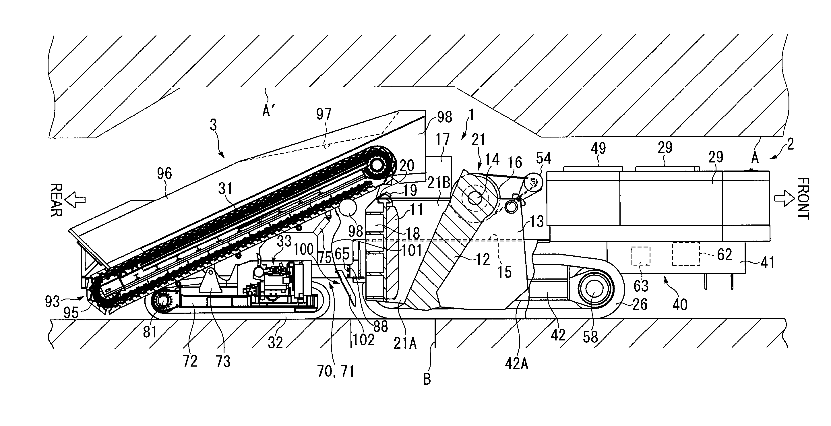
[0015]Since the mobile crusher includes the crusher vehicle and the feeder vehicle that travel independently according to the aspect of the invention, the entire length of each vehicle can be sufficiently reduced and thus the turning radius can be reduced. Accordingly, the mobile crusher can favorably turn at intersections in tunnels in an underground mine. Also, since the crusher vehicle and the feeder vehicle include the crusher-side connecting portion and the feeder-side connecting portion, the crusher vehicle and the feeder vehicle can be accurately positioned by connecting the crusher-side connecting portion to the feeder-side connecting portion during crushing operation. Thus, the objects conveyed from the transfer device can be reliably inputted into the crushing device and therefore the crushing operation can be favorably conducted.
[0047]Since the slide mechanism is provided according to the above arrangement, the crushing device can be slid to be spaced away from the feeder unit. Thus, the feeder unit can swing without interference with the crushing device. During crushing operation, the feeder unit is disposed so that the distal end thereof is positioned above the crushing device while overlapping the crushing device as viewed from the above because it is required to transfer the objects into the crushing device. When the feeder unit swings in such a posture during movement, the feeder unit may interfere with the crushing device. According to the aspect of the invention, such interference can be reliably prevented.

Problems solved by technology

The fixed crusher 504 needs to be moved every time a place to be quarried is changed from the vicinity of one of the ore paths B to the vicinity of another ore path B, thus causing cumbersome work.
However, such a mobile crusher is tall, so that it is difficult to install the mobile crusher at a mining point having a limited working space such as a tunnel in an underground mine.
However, even when the mobile crusher disclosed in Patent Document 2 is used, the mobile crusher including the hopper, the transfer device, the crushing device and a power line for driving various devices is still too long as a whole.
Further, since the width and height of the tunnel A3, A4 or A5 are minimally reduced, it is difficult for the mobile crusher to make a turn quickly even at the obtuse-angled corners.
However, such a crushing plant is too tall and thus cannot move freely in tunnels.
Also, it is difficult to accurately position the transfer device relative to the crushing device, thus taking considerable time to start crushing operation.
When the feeder unit swings in such a posture during movement, the feeder unit may interfere with the crushing device.

Method used


Image

  • Self-propelled crushing system
  • Self-propelled crushing system
  • Self-propelled crushing system

Examples


first exemplary embodiment

[0071]A first exemplary embodiment of the invention will be described below with reference to the attached drawings.

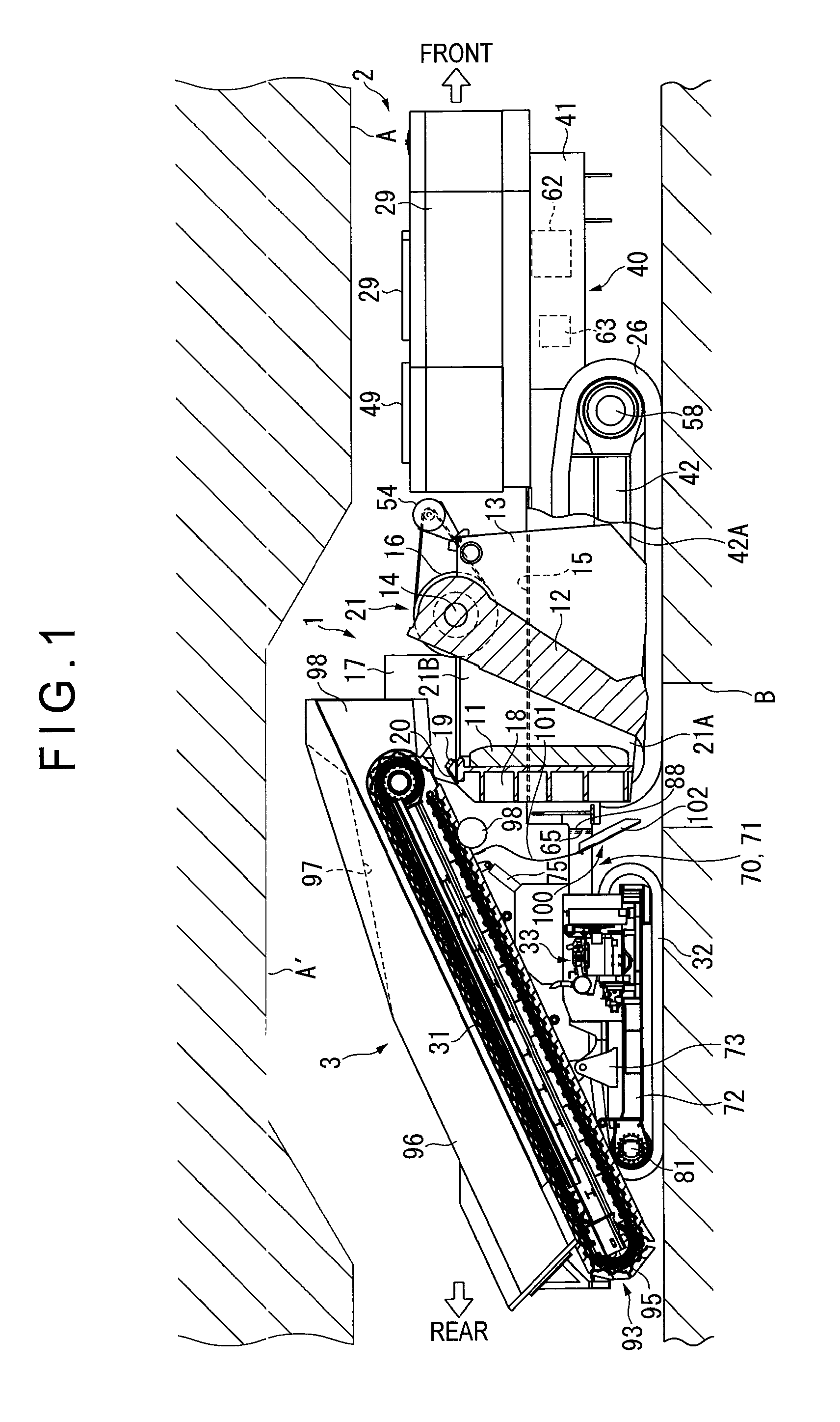
[0072]FIG. 1 shows a mobile crusher 1 of the first exemplary embodiment during operation, which is also a cross sectional view taken along line I-I in FIG. 2. FIG. 2 is a plan view showing the mobile crusher 1. FIG. 3 shows a crusher vehicle 2 of the mobile crusher 1 as viewed from the front side. FIG. 4 is a plan view showing a front portion of a feeder vehicle 3 of the mobile crusher 1, and FIG. 5 shows the feeder vehicle 3 as viewed from the front side. FIG. 6 shows a hydraulic circuit used for the mobile crusher 1. In FIGS. 1, 2 and 4, the right side will be referred to as a front side and the left side will be referred to as a rear side according to this exemplary embodiment.

1. Brief Description of Mobile Crusher

[0073]As shown in FIGS. 1 and 2, the mobile crusher 1 includes the crusher vehicle 2 and the feeder vehicle 3 connected to each other in the front-rear di...

second exemplary embodiment

[0120]As shown in FIGS. 11 and 12, the mobile crusher 200 of the second exemplary embodiment is installed in the tunnel A in an underground mine or the like to crush objects to be crushed such as rocks and input the crushed objects into the ore path B provided on a road. More specifically, the mobile crusher 200 includes: a vehicle body 210 provided over the ore path B; a feeder unit 220 provided on the rear side of the vehicle body 210; and a power unit 230 provided on the front side of the vehicle body 210. Here, the ore path B is a pit for guiding crushed objects from a tunnel on which crushing operation is conducted to another tunnel provided on a lower layer.

[0121]The vehicle body 210 includes a body frame 211 extending in the front-rear direction. The body frame 211 includes a main frame 212 that is substantially frame-shaped in plan view and traveling frames 213 provided on the right and left sides of the main frame 212. A crushing device 214 that is hydraulically driven is m...

third exemplary embodiment

[0145]In a mobile crusher 300 of the second exemplary embodiment as shown in FIGS. 15 to 17, the support frame 223 supporting the feeder unit 220 is fixed directly to the rear end of the main frame 212. Accordingly, the feeder unit 220 does not swing right or left. Instead, a power unit support 219 is provided on the front end of the main frame 212. The power unit 230 is swingably supported on the power unit support 219 via the swing circle 218 serving as the swing unit.

[0146]One end of a power unit swing cylinder 239 is attached to the main frame 212 while the other end of the power unit swing cylinder 239 is attached to the base frame 231 of the power unit 230. The extension and contraction of the power unit swing cylinder 239 swings the power unit 230 relative to the vehicle body 210.

[0147]Incidentally, the crushing device 214 does not interfere with the feeder unit 220 because the feeder unit 220 does not swing in the third exemplary embodiment. Thus, a slide mechanism for slidi...


PUM


Abstract

A mobile crushing system is for crushing inputted objects and dropping the crushed objects directly into an ore path. The mobile crushing system includes a crusher vehicle on which a crushing device for crushing the objects is mounted and which includes carriers, and a feeder vehicle on which a transfer device for transferring the objects to the crushing device and which includes carriers. The crusher vehicle and the feeder vehicle travel independently and include a crusher-side connecting portion and a feeder-side connecting portion that are connected to each other. During crushing operation, the ore path is interposed between the crusher vehicle and the feeder vehicle in the front-rear direction.

Description

TECHNICAL FIELD[0001]The present invention relates to a mobile crusher that is movably installed, for example, in tunnels in a mine.[0002]As shown in FIG. 20, tunnels A extending horizontally are typically connected to mining points 500 under the ground. Tunnels A1 vertically adjacent to each other are connected via connecting tunnels A2 that extend upward and downward. Ore paths (ore input openings) B into which ores are dropped are provided on the tunnels A1. The ore paths B are combined together so that a fixed crusher (not shown) is provided in the vicinity of the exit of the combined ore path. Ores crushed by the fixed crusher are temporarily stored in a reservoir 501. The ores stored in the reservoir 501 are dropped into a bucket 503 via a conveyor 502 provided on a lower portion of the reservoir 501 for every predetermined amount, and are pulled up by the bucket 503 to the ground.[0003]In recent years, the mining points 500 are not only vertically provided at plural positions...

Claims


Application Information

Patent Timeline
Patent Type & Authority Applications(United States)
IPC IPC(8): B02C23/02
CPCB02C21/026B02C23/02
Inventor YAMADA, MITSUNOBUKANDA, TOSHIMASAUMEDA, HIROYUKIIIZUKA, KOYANAKAMURA, MASARUUETAKE, MASAAKI
Owner KOMATSU LTD
Why Eureka
Eureka Blog
Learn More