
Fuel cell vehicle

a fuel cell and component technology, applied in the direction of battery/cell, electric propulsion mounting, electrochemical generator, etc., can solve the problems of insufficient suitability of prior art component layout or prior art configuration, and achieve the effect of preventing accumulation of hydrogen gas, facilitating smooth introduction, and increasing heigh

Active Publication Date: 2010-05-13
TOYOTA JIDOSHA KK
View PDF10 Cites 18 Cited by
  • Summary
  • Abstract
  • Description
  • Claims
  • Application Information

AI Technical Summary

Benefits of technology

[0007]In the fuel cell vehicle according to this aspect of the invention, at least part of the fluid distributor used to distribute the supply of the fluid to the fuel cell stack is located in the center tunnel. Various fluid pipes attached to the fluid distributor can thus be efficiently located in the center tunnel. This arrangement desirably enhances the space efficiency. The arrangement of locating at least part of the fluid distributor in the center tunnel also allows the center tunnel to be efficiently used for various fluid pathways connecting with the fluid distributor.
[0030]In another preferable application of the fuel cell vehicle according to the above aspect of the invention, the floor panel is formed to have a greater height at a location closer to the center tunnel in the vehicle width direction in at least an installation area of the fuel cell stack in the front-rear direction of the vehicle. For example, in the event of leakage of the hydrogen gas during a fuel cell inactive time or during a long storage time, this arrangement advantageously enables the leaked hydrogen gas to be smoothly introduced from outside of the center tunnel into the center tunnel and released out.

Problems solved by technology

The prior art component layout or the prior art configuration is, however, not sufficiently suitable for a fuel cell system including a fluid distributor designed to distribute a fluid in a vehicle width direction.

Method used


Image

  • Fuel cell vehicle
  • Fuel cell vehicle
  • Fuel cell vehicle

Examples


first embodiment

A. Component Layout of Fuel Cell System in First Embodiment of the Invention

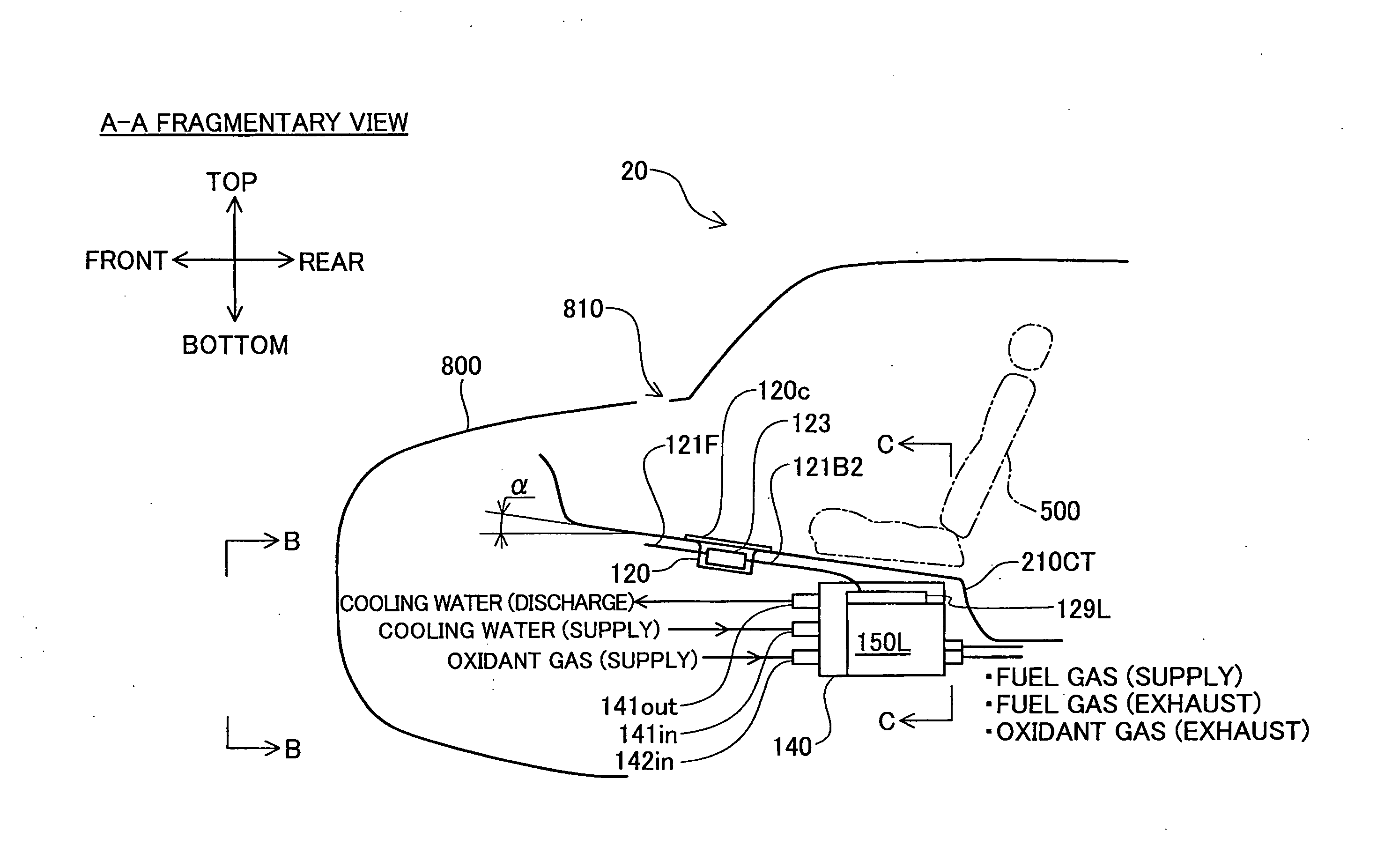
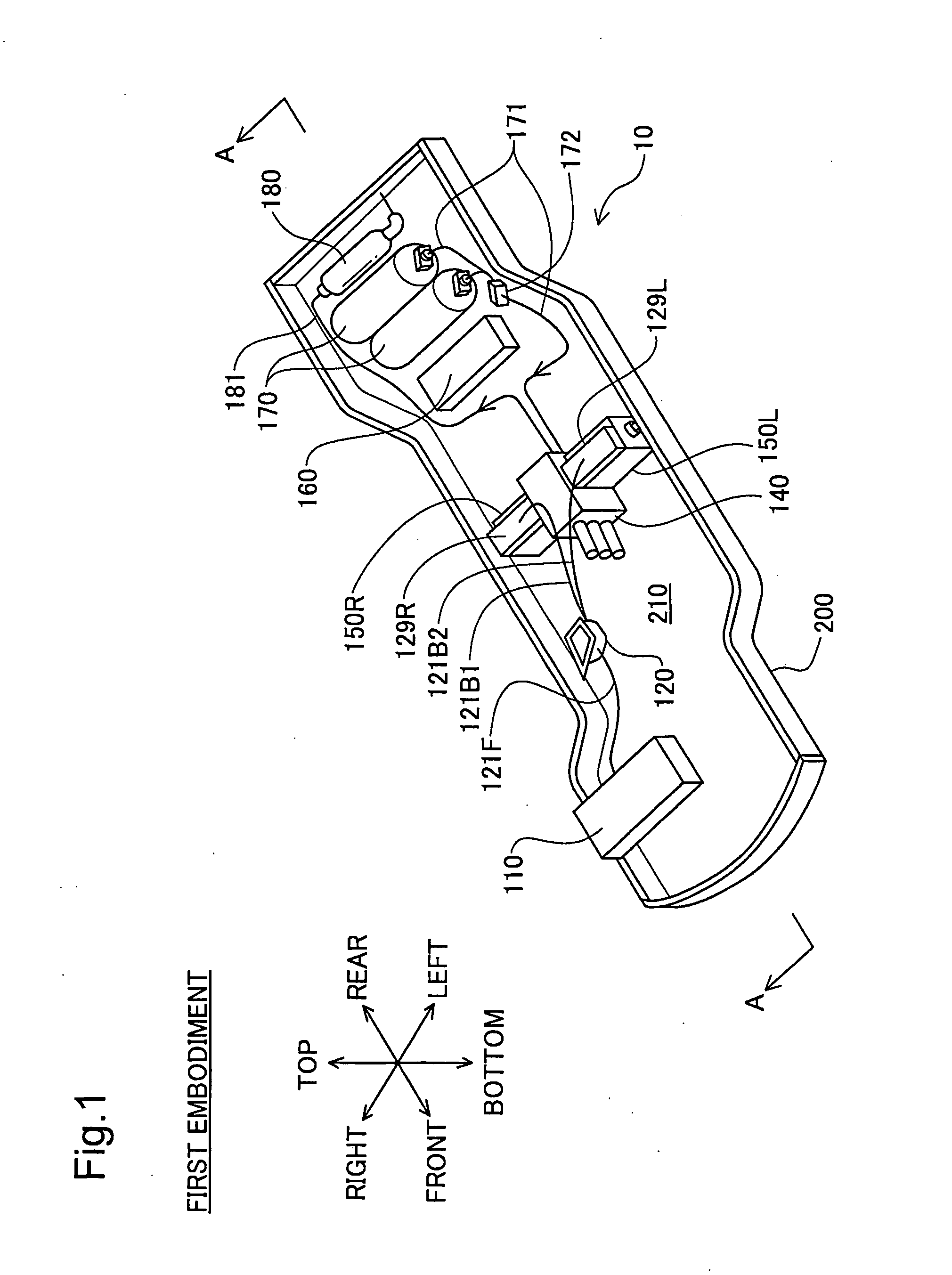
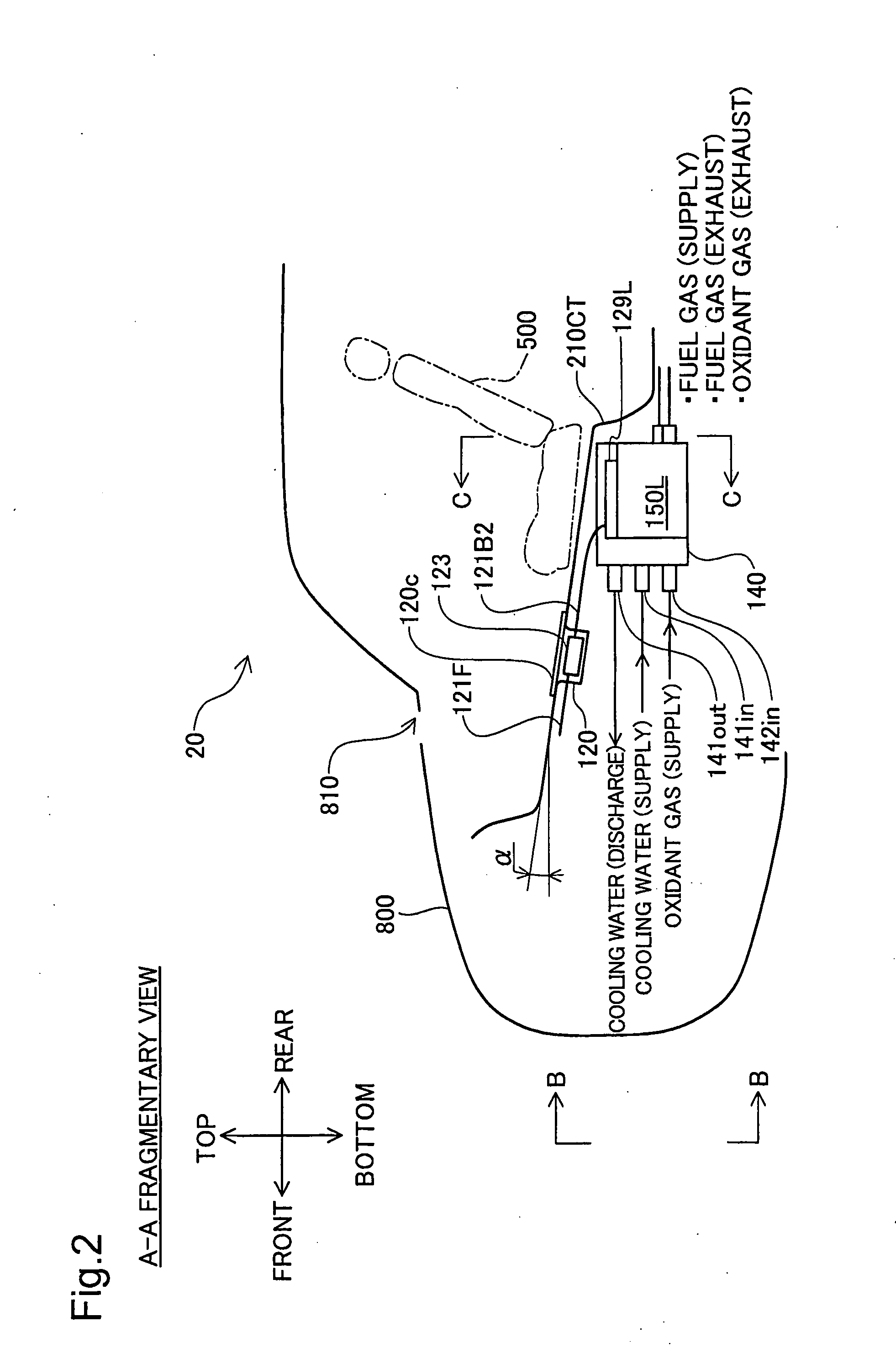
[0049]FIG. 1 is an explanatory view illustrating the configuration of a chassis 10 of a fuel cell vehicle or a vehicle equipped with a fuel cell system in a first embodiment of the invention. The chassis 10 includes a frame 200, a floor panel 210, a power control unit 110, two hydrogen tanks 170, a secondary battery 160, a high voltage relay box casing 120, a muffler 180, a fluid distributor 140, two fuel cell stacks 150L and 150R, and two high voltage components 129L and 129R.

[0050]A fuel gas (hydrogen gas) supplied from the two hydrogen tanks 170 goes through a hydrogen supply conduit 171 and a regulator 172 and enters the fluid distributor 140. The fluid distributor 140 distributes the supply of the fuel gas into individual anodes (not shown) included in the two fuel cell stacks 150L and 150R that are respectively connected with a left side and a right side of the fluid distributor 140. An anode off gas f...

second embodiment

B. Component Layout of Fuel Cell System in Second Embodiment of the Invention

[0080]FIGS. 11 and 12 are explanatory views illustrating the component layout of a fuel cell system in a second embodiment of the invention. The difference of the component layout of the second embodiment from that of the first embodiment is that two fuel cell stacks 150Lb and 150Rb having fuel cells stacked in the vehicle width direction of the chassis 10 are located behind a rear panel 230 provided on the rear side of a seat 500 and are inclined to the stacking direction along an inclination of the rear panel 230. The two fuel cell stacks 150Lb and 150Rb are respectively connected with a left side and a right side of a fluid distributor 140b that is also provided behind the rear panel 230 in an inclined orientation. The substantially symmetrical arrangement of the fuel cell stacks 150Lb and 150Rb on the left side and the right side of the fluid distributor 140b equalizes the weight balance between the lef...


PUM

PropertyMeasurementUnit
widthaaaaaaaaaa
pressureaaaaaaaaaa
heightaaaaaaaaaa

Abstract

In a fuel cell vehicle of the present invention, a floor panel is constructed to have a center tunnel formed to extend in a front-rear direction of the vehicle. A fluid distributor provided below the floor panel is at least partly located in the center tunnel and is operative to distribute a supply of a fluid in a vehicle width direction. At least one fuel cell stack is provided adjacent to the fluid distributor in the vehicle width direction below the floor panel and is operative to receive the distributive supply of the fluid from the fluid distributor. This fuel cell system has an efficient component layout from the total standpoint of the operability and the space efficiency.

Description

TECHNICAL FIELD[0001]The present invention relates to the configuration of and the component layout in a fuel cell vehicle.BACKGROUND ART[0002]A proposed component layout of a fuel cell system for a fuel cell vehicle lays out various components under the floor of a passenger compartment of the vehicle, while assuring the sufficiently wide space for the passenger compartment (see, for example, JP-A-2006-36117).[0003]The prior art component layout or the prior art configuration is, however, not sufficiently suitable for a fuel cell system including a fluid distributor designed to distribute a fluid in a vehicle width direction.DISCLOSURE OF THE INVENTION[0004]In order to solve the problem of the prior art discussed above, there would thus be a demand for providing a technique of actualizing an efficient component layout of a fuel cell system in a fuel cell vehicle.[0005]The present invention accomplishes at least part of the demand mentioned above and the other relevant demands by a f...

Claims


Application Information

Patent Timeline
Patent Type & Authority Applications(United States)
IPC IPC(8): B60R16/04H01M8/04
CPCB60K1/04B60L50/71B60K2001/0416B60K2001/0422B60K2001/0438H01M8/04029H01M8/04089H01M8/04955H01M8/2415H01M8/2465H01M2250/20Y02T90/32Y02T90/34H01M8/2484B60L50/72B60K15/07Y02T90/40Y02E60/50
Inventor JUFUKU, YASUNOBUARISAWA, HIROSHI
Owner TOYOTA JIDOSHA KK
Learn More