
Pneumatic Tire

a technology of pneumatic tires and tyres, which is applied in the field of pneumatic tires, can solve the problems of insufficient suppression, lowering durability, and reducing the risk of running into a malfunction, so as to suppress heat generation, enhance durability, and inhibit separation

Active Publication Date: 2010-05-13
TOYO TIRE & RUBBER CO LTD
View PDF23 Cites 4 Cited by
  • Summary
  • Abstract
  • Description
  • Claims
  • Application Information

AI Technical Summary

Benefits of technology

[0008]Accordingly, an object of the present invention is to provide a pneumatic tire which can achieve excellent durability and handling performance while arranging a white rubber in a side wall portion.
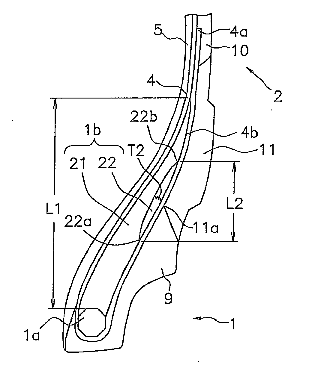
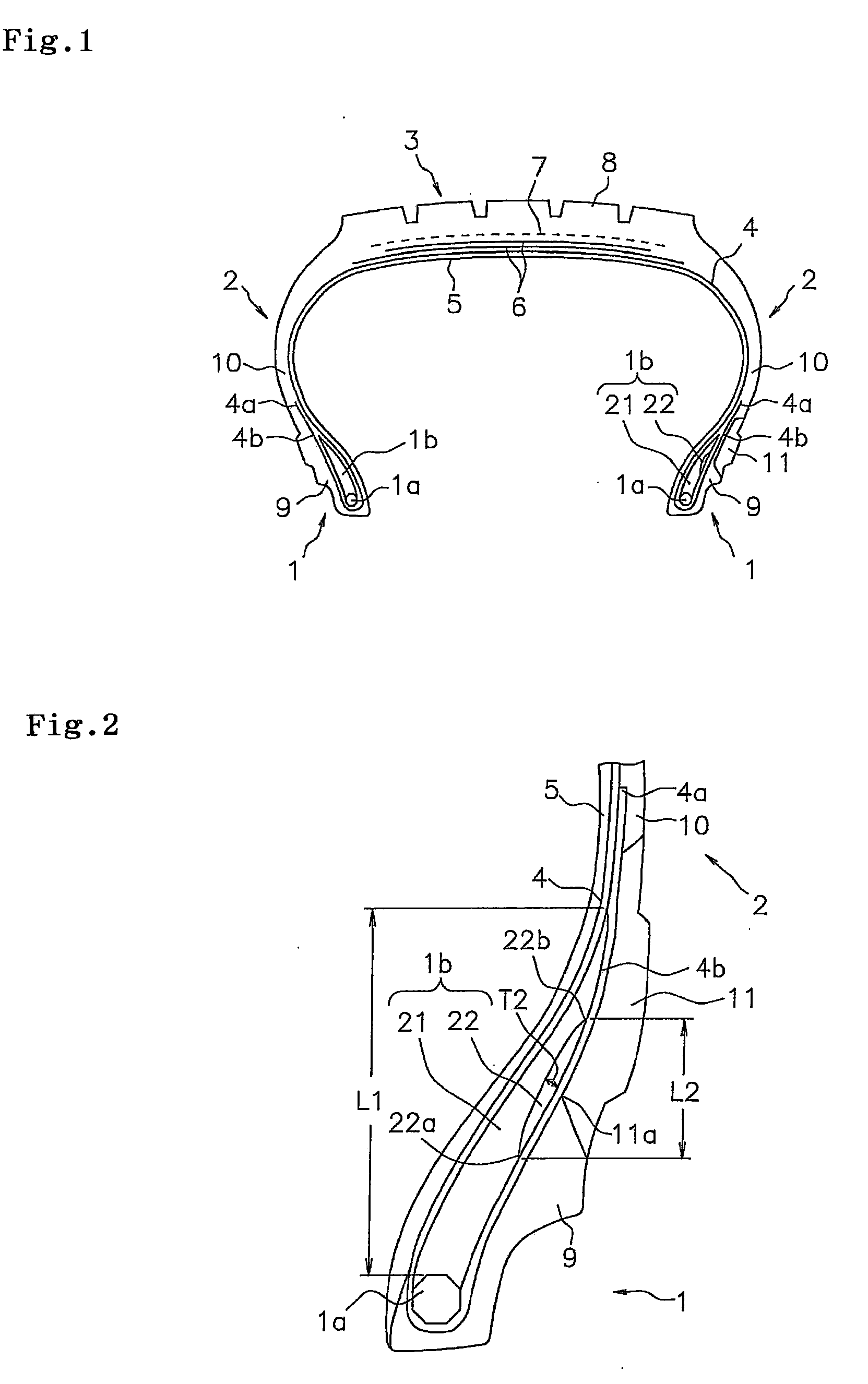
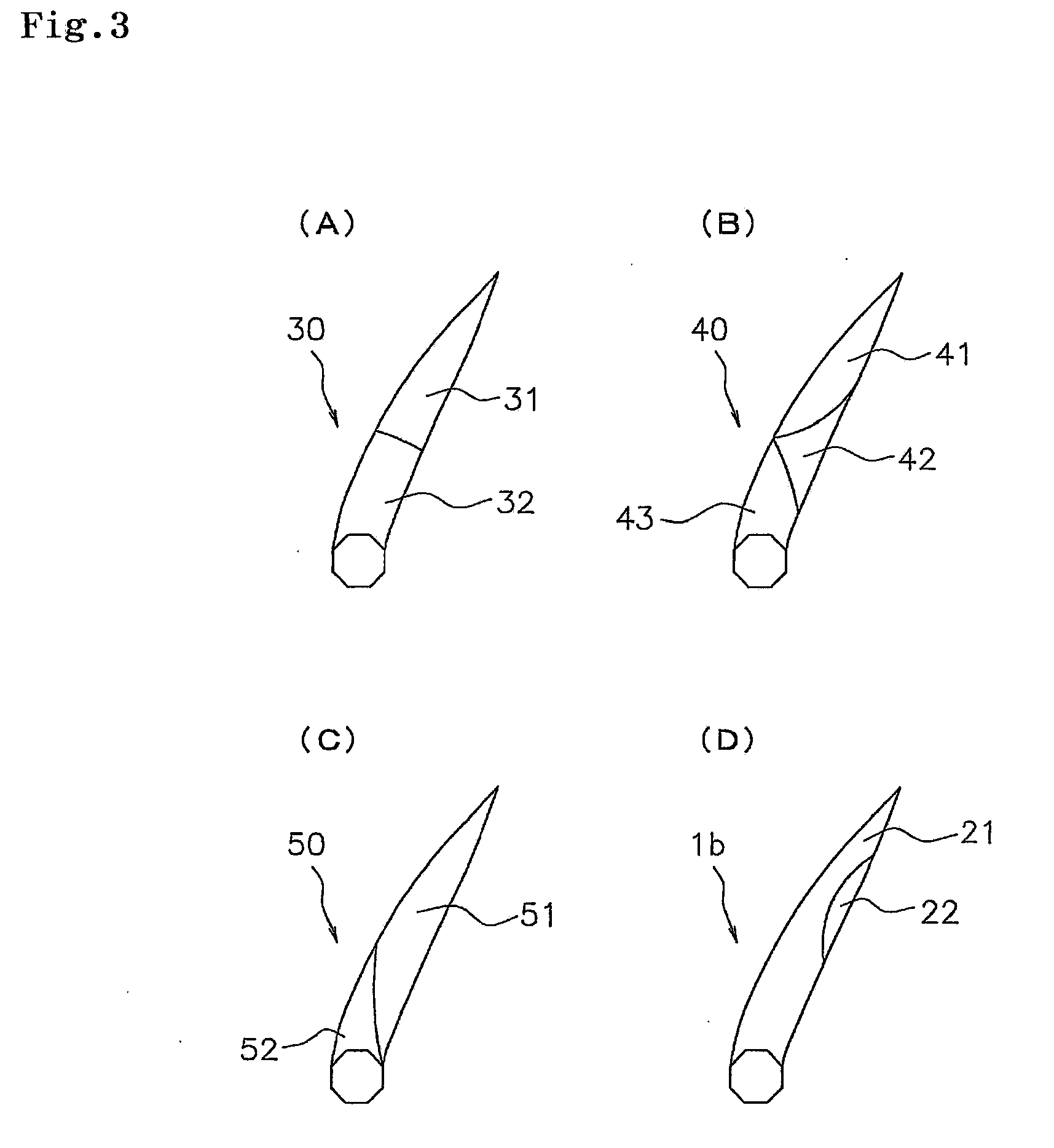
[0010]In the pneumatic tire according to the present invention, since the bead filler has the soft rubber portion as mentioned above, it is possible to absorb the strain which tends to be concentrated on the interface between the inner peripheral end of the white rubber and the rubber jointed thereto, and it is possible to inhibit the separation from being generated so as to enhance the durability (the general durability). Further, since the main body rubber portion from the leading end of the bead filler to the bead core is comparatively hard, it is possible to suppress the heat generation rise caused by the standing wave at the high speed region so as to enhance the durability (the high speed durability), and it is possible to secure the rigidity of the side wall portion so as to achieve the excellent handling performance.
[0011]In the above structure, it is preferable that a rate of a cross sectional height of the soft rubber portion with respect to the bead filler is between 30 and 50%. It is possible to secure the cross sectional height of the soft rubber portion so as to effectively achieve the absorbing action of the strain by making this rate equal to or more than 30%, whereby it is possible to more securely enhance the general durability. Further, it is possible to secure the volume of the main body rubber portion by making the rate equal to or less than 50%, whereby it is possible to more securely enhance the high-speed durability and the handling performance. The cross sectional heights of the bead filler and the soft rubber portion can be measured in the tire meridian cross section.
[0012]In the above structure, it is preferable that a rate of a cross sectional area of the soft rubber portion with respect to the bead filler is less than 30%. It is possible to secure the rate occupied by the main body rubber portion with respect to the bead filler by making the rate less than 30%, whereby it is possible to more securely enhance the high-speed durability and the handling performance. The cross sectional areas of the bead filler and the soft rubber portion can be measured in the tire meridian cross section.

Problems solved by technology

Therefore, a strain generated near the bead portion due to repeated compression and tension at a time of traveling tends to be concentrated on an interface between the white rubber and a rubber jointed thereto, and causes a separation of a roll-up ply, and there is a risk of running into a malfunction.
However, according to this method, since there is a tendency that a member thickness corresponding to the stuck reinforcing tape is increased and a heat generation characteristic rises up, there is a problem that a durability is lowered under a high-speed traveling condition in which an amount of heat generation near the bead portion rises.
However, since these tires accompany a low rigidity of the side wall portion caused by a significant reduction in hardness of the bead filler, it is not possible to sufficiently suppress a heat generation rise caused by a standing wave in a high speed region, and there is a risk that a deterioration of high-speed durability is caused.
Further, there is a risk that a handling performance is lowered by the low rigidity of the side wall portion.

Method used


Image

  • Pneumatic Tire
  • Pneumatic Tire
  • Pneumatic Tire

Examples


example

[0033]An example tire which concretely shows the structure and effect of the present invention will be explained. An evaluation of each of performances is executed as follows.

[0034](1) General Durability

[0035]A general performance test was carried out in accordance with a method prescribed in JISD4230. In the case where such a malfunction as a separation or the like is not recognized even after the end of a test stage 3, load is continuously given to the tire, and the driving distance until the malfunction is recognized were measured.

[0036](2) High Speed Durability

[0037]A high speed performance test A was carried out in accordance with a method prescribed in JISD4230. In the case where such a malfunction as a separation or the like is not recognized even after the end of a test stage 6, the speed is continuously given to the tire (per 10 minutes), and the speed and the time until the malfunction is recognized were measured.

[0038](3) Handling Characteristic and Ride Comfort

[0039]Thes...


PUM

PropertyMeasurementUnit
heightaaaaaaaaaa
thicknessaaaaaaaaaa
hardnessaaaaaaaaaa

Abstract

A pneumatic tire has an annular bead core, a bead filler, a carcass ply rolled up in such a manner as to pinch the bead core and the bead filler, and a white rubber arranged in an outer side of the carcass ply of the side wall portion. The white rubber has an inner peripheral end positioned in an outer side of the bead filler. The bead filler has a main body rubber portion running into the bead core from a leading end, and a soft rubber portion constructing a part of an outer surface of the bead filler and positioned in an inner side of the inner peripheral end of the white rubber. The soft rubber portion is harder than the white rubber and softer than the main body rubber portion.

Description

BACKGROUND OF THE INVENTION[0001]1. Field of the Invention[0002]The present invention relates to a pneumatic tire in which a white rubber is arranged in a side wall portion.[0003]2. Description of the Related Art[0004]Conventionally, in a tire which is mainly used in a high load vehicle such as a recreational vehicle (RV) or a light truck (LT) or the like, there has been known a pneumatic radial tire in which various white patterns are formed by a white rubber which is arranged in a side wall portion, and a fashion characteristic is enhanced (for example, refer to Japanese Unexamined Patent Publication Nos. 9-111041 and 2008-1742). The white rubber is generally arranged in a region which is closer to a bead portion than a tire maximum width position at which a deflection at a time of traveling is great.[0005]The white rubber cannot employ a carbon black having a high reinforcing characteristic for holding the white color, and is accordingly softer and lower in rigidity than a normal...

Claims


Application Information

Patent Timeline
Patent Type & Authority Applications(United States)
IPC IPC(8): B60C13/04
CPCB60C13/04B60C15/0607B60C2015/0614Y10T152/10837Y10T152/10846Y10T152/10504
Inventor YOSHIKAWA, MAKOTO
Owner TOYO TIRE & RUBBER CO LTD
Learn More