
Finger vein authentication device

a finger vein and authentication technology, applied in the field of finger vein authentication devices, can solve the problems of preventing the correct authentication, affecting the accuracy of finger authentication, so as to prevent deterioration in authentication accuracy, high accuracy, and boost the reproducibility of finger authentication

Active Publication Date: 2010-04-22
HITACHI INFORMATION & CONTROL SOLUTIONS LTD
View PDF4 Cites 19 Cited by
  • Summary
  • Abstract
  • Description
  • Claims
  • Application Information

AI Technical Summary

Benefits of technology

[0009]The finger vein authentication device of this invention contains a structure for stabilizing the finger and is moreover capable of providing a compact and highly accurate finger vein authentication device by preventing adverse effects from the left and right fingers.
[0012]The present invention boosts the reproducibility of the submitted finger. A compact and highly accurate finger vein authentication device is also achieved by preventing deterioration in the authentication accuracy caused by the fingers on the left and right of the finger for authentication.

Problems solved by technology

Moreover, pressing the fingertips strongly might destroy the blood vessel pattern and so sometimes prevent obtaining the correct authentication results.
In the method for irradiating light from the left and right sides of the finger as disclosed in Japanese Patent Application Laid-Open Publication No. 2004-265269, adverse effects sometimes occurred such as being unable to capture a sharp vein image due to fingers other than the authentication finger blocking the light source, and light reflecting from fingers other than the authentication finger.
The compact finger vein authentication devices of the related art failed to consider a device structure for stabilizing the finger submitted for authentication, and the adverse effects from the other fingers not for authentication.

Method used


Image

  • Finger vein authentication device
  • Finger vein authentication device
  • Finger vein authentication device

Examples


first embodiment

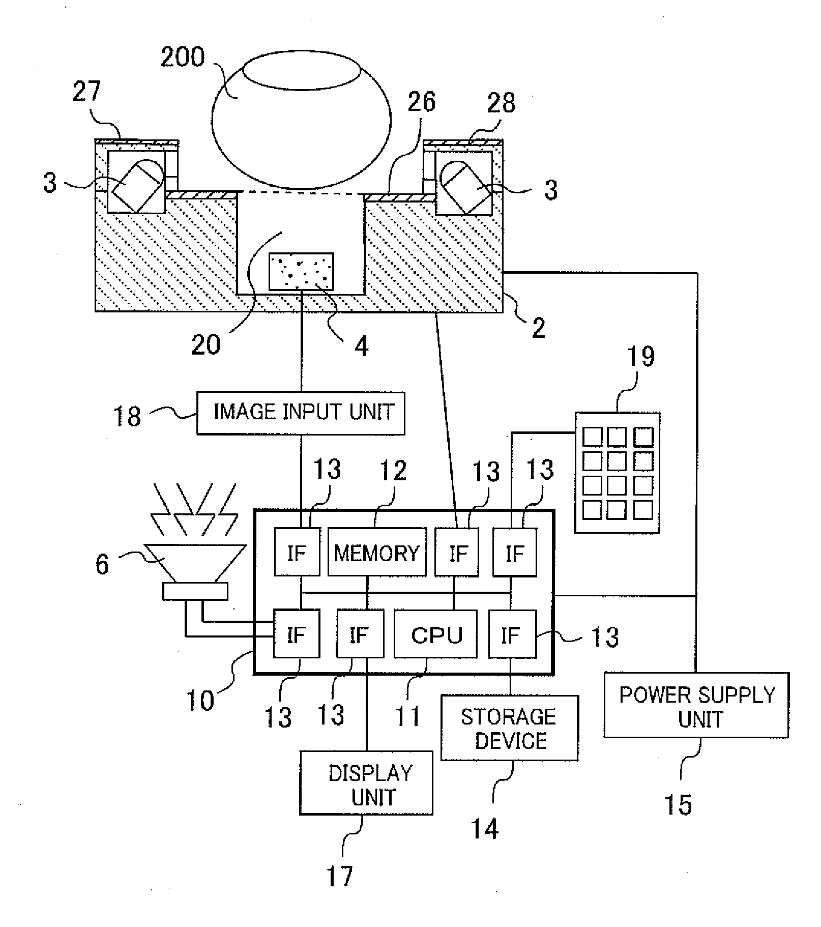
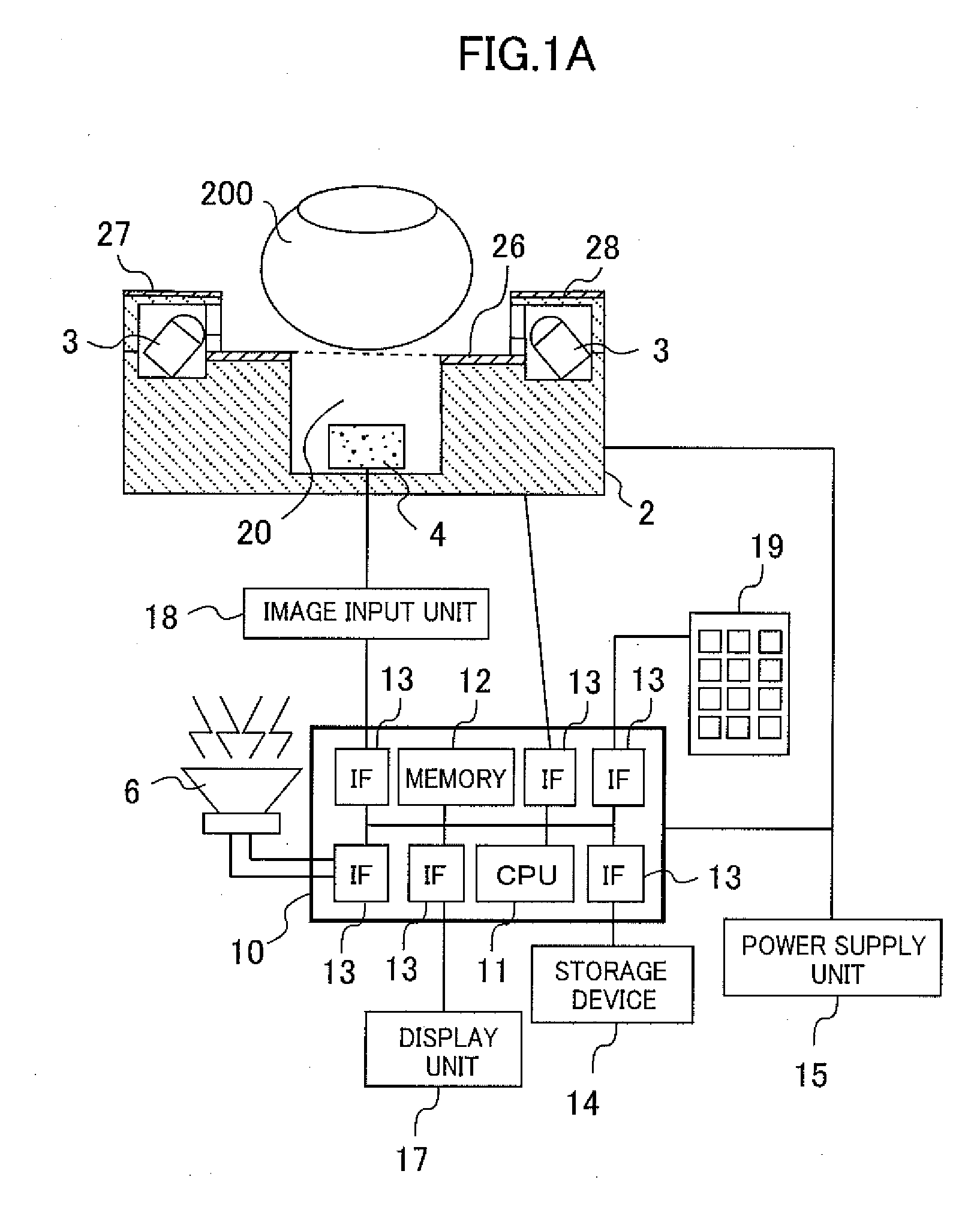
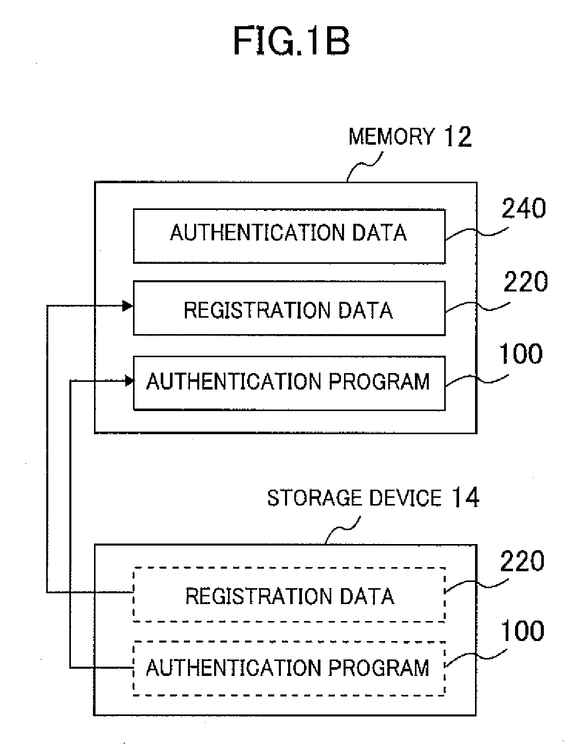
[0031]FIG. 1A is a block diagram of the authentication device of the first embodiment. FIG. 1B is a drawing showing the internal sections of the memory 12 and the storage device 14 serving as the storage unit within the authentication system of the first embodiment.

[0032]This authentication system (device) includes: a finger vein data acquisition device 2, an image input unit 18, an authentication processor unit 10, a storage device 14, a display unit 17, an information input unit 19, an audio output unit 6 and a power supply unit 15.

[0033]The finger vein data acquisition device 2 is one case, and contains a light source 3, an image capture device 4, a center finger stand 26, a left finger stand 27, and a right finger stand 28. The light source 3 is for example an infrared ray emitting diode (Light Emitting Diode: LED). The light source 3 emits infrared light onto a finger 200 placed on the center finger stand 200. The image capture unit 4 captures an image of the mounted finger 200...

second embodiment

[0074]In the second embodiment, the registration data that is registered in one authentication device is limited to one case, or in other words, the authentication device performs a one-to-one authentication (1 registered person: 1 registration data). The process is described next using the case where the authentication device is built for example into a locker. This type of device cannot be used simultaneously by more than one person. In the case of a public locker for example, the information is registered when locking the locker and no one except the registered party can utilize the locker until the next time the locker is opened. The authentication device in other words stores only the registration data of the last registered user, and authenticates only one registration data case.

[0075]The light control S103 of the first embodiment is improved in the second embodiment and the S103 processing time is shortened. These changes allow using an inexpensive CPU with a slower processin...

third embodiment

[0082]The third embodiment is an authentication system including a function to check that the user finger is correctly placed. The following description is made using FIGS. 7A to 7F. FIG. 7A is a drawing showing the state where the finger 200 is correctly placed. FIG. 7B is a cross sectional view taken along straight line A in FIG. 7A. FIG. 7D and FIG. 7E are drawings showing the state where the finger 200 is not correctly placed. FIG. 7C and FIG. 7F are drawings showing examples of images captured by the image capture unit 4.

[0083]The authentication device of this embodiment includes a projection 21 for setting the fingertip position. The user mounts the fingertip aligning it with the position of the projection 21 as shown in FIG. 7A. The finger can in this way be mounted at the same position during registration and during authentication to make highly accurate authentication possible. However a user that is not accustomed to using the device might sometimes mistakenly mount the fi...


PUM


Abstract

A compact and highly accurate downward irradiation type finger vein authentication device achieved by providing a structure that stabilizes the finger and also prevents adverse effects caused by the left and right fingers. The finger vein authentication device comprises a center finger stand for mounting the finger for authentication; a light source for irradiating infrared light onto the finger; an image capture unit for capturing an image of the finger veins by way of light from a light source; an aperture to open in the image capture direction of the image capture unit; a storage device to store the finger biological information; an authentication processor unit to extract the features from the image captured by the image capture unit and match the features with the biological information stored in the storage device; and a left and right finger stand for the fingers on the left and right of the finger for authentication. This left and right finger stand is installed at a position somewhat higher than the center finger stand. This left and right finger stand is also made from a light blocking member and a light source is installed in the lower section.

Description

CLAIM OF PRIORITY[0001]The present invention claims priority from Japanese patent application JP2008-268750 filed on Oct. 17, 2008, the content of which is hereby incorporated by reference into this application.BACKGROUND OF THE INVENTION[0002]The present invention relates to an individual authentication device, and relates in particular to technology for utilizing vein patterns obtained by capturing an image of light that passed through the body.[0003]The security of personal information has become viewed as in issue of major importance in recent years. Biometrics authentication has become the focus of much attention as a personal authentication technology for safeguarding security. Biometrics is authentication technology that utilizes the biological information of humans, and is excellent in terms of both convenience and security.[0004]Biometrics authentication technology known in the related art performs authentication by utilizing fingerprints, the iris (of the eye), the voice, ...

Claims


Application Information

Patent Timeline
Patent Type & Authority Applications(United States)
IPC IPC(8): G06K9/00G06V10/141G06V40/145
CPCG06K9/00013G06K9/00912G07C9/00896G06K2009/00932G07C9/00563G06K9/2027G06V40/67G06V40/14G06V10/141G06V40/145
Inventor KIYOMIZU, HARUMIMIURA, NAOTOMIYATAKE, TAKAFUMINAGASAKA, AKIO
Owner HITACHI INFORMATION & CONTROL SOLUTIONS LTD
Learn More