Attachment member and method for manufacturing the same
a technology of attachment members and components, applied in the field of attachment members, can solve the problems of unsuitable prior art attachment members for most purposes, unsuitable for wrapping an object around another object, and inability to easily cut attachment members when attached to the commodity
- Summary
- Abstract
- Description
- Claims
- Application Information
AI Technical Summary
Benefits of technology
Problems solved by technology
Method used
Image
Examples
second embodiment
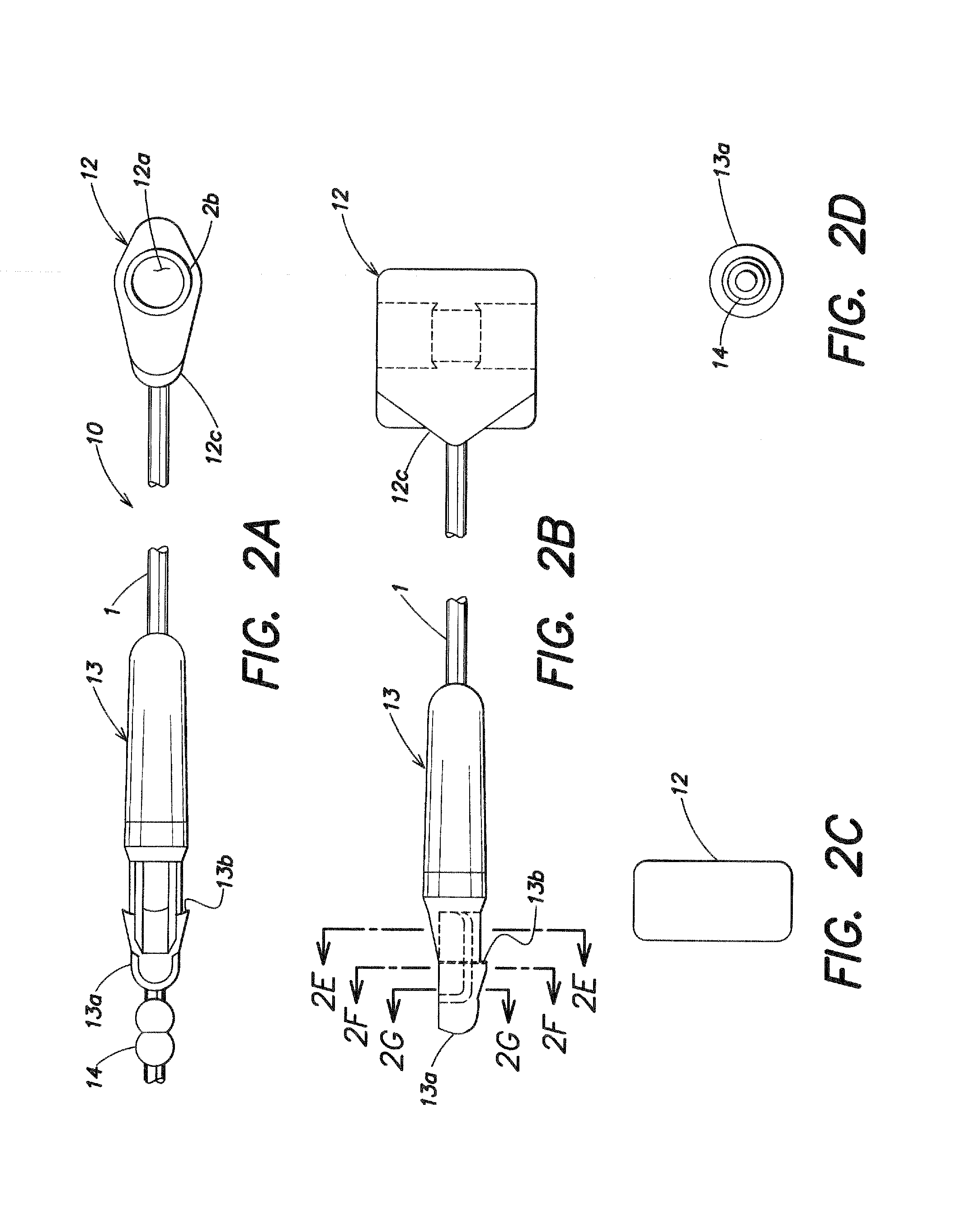
[0068]FIGS. 2A-2H show an attachment member in accordance with the invention that is designated generally as 10 and includes a receiving section 12 having a receiving hole 12a that extends in a direction substantially perpendicular to a longitudinal direction of the elongate member 1. An engaging portion 12b is formed as an annular flange inside the receiving hole 12a (see FIG. 2A). An insertion section 13 is indented or cut halfway along its length to form a head portion 13a which is located at an end of the insertion section 13, and an engaging portion 13b is formed on a remaining part of the head portion 13a. As shown in FIG. 2A, there is a stopper 14 which is a part of the elongate member 1 formed continuously or integrally with the head portion 13a of the insertion section 13 by, for example, extrusion molding as described later. The stopper 14 is arranged in a receiving bulge portion 12c of the receiving section 12 formed on a side of the receiving section 12 continuous or int...
third embodiment
[0069]Referring now to FIGS. 3A-3G, an attachment member in accordance with the invention is designated generally as 30 and includes a receiving section 32 having a receiving hole 32a and a pair of opposing engaging portions 32b (see FIG. 3G), and an insertion section 33 that extends in a direction substantially perpendicular to a longitudinal direction of the elongate member 1. Insertion section 33 includes a head portion 33a and a step-like engaging portion 33b formed at a base of the head portion 33a. In this case, an assembly is formed by providing a plurality of the attachment members 30 in parallel with each other at substantially constant intervals and connecting the receiving sections 32 and the insertion sections 33 to runner members 35 through connecting portions 35a. The runner members 35 and connecting portions 35a are preferably made of polypropylene and can be cut, e.g., to enable separation of the attachment members 30 from the runner members 35. The runner members 35...
fourth embodiment
[0070]Referring now to FIGS. 4A-4H, an attachment member in accordance with the invention is designated generally as 40 and includes a receiving section 42 having a receiving hole 42a and a pair of opposing engaging portions 42b, and an insertion section 43 that extends in a direction substantially perpendicular to a longitudinal direction of the elongate member 1. Insertion section 43 includes a step-like engaging portion 43b formed at a base of a head portion 43a. An assembly is formed by providing a plurality of the attachment members 40 in parallel with each other at substantially constant intervals and connecting the receiving sections 42 and the insertion sections 43 to runner members 45 through connecting portions 45a. The runner members 45 and connecting portions 45a are preferably made of polypropylene and can be cut, e.g., to enable separation of the attachment members 40 from the runner members 45. The runner members 45 on each side of the attachment members 40 are substa...
PUM
| Property | Measurement | Unit |
|---|---|---|
| length | aaaaa | aaaaa |
| diameter | aaaaa | aaaaa |
| elastomeric | aaaaa | aaaaa |
Abstract
Description
Claims
Application Information
 - R&D
- Intellectual Property
- Life Sciences
- Materials
- Tech Scout
- Unparalleled Data Quality
- Higher Quality Content
- 60% Fewer Hallucinations
Browse by: Latest US Patents, China's latest patents, Technical Efficacy Thesaurus, Application Domain, Technology Topic, Popular Technical Reports.
© 2025 PatSnap. All rights reserved.Legal|Privacy policy|Modern Slavery Act Transparency Statement|Sitemap|About US| Contact US: help@patsnap.com


