
Total internal reflection lens for color mixing

a color mixing and internal reflection technology, applied in the field of lighting equipment, can solve the problems of non-uniform color distribution, affecting the design of light sources such as spot lights and other general lighting applications, and reducing the light intensity output of light emitting devices by 40% to 50%, and achieve the effect of simplifying the manufacturing process

Active Publication Date: 2010-04-15
LEDENGIN
View PDF91 Cites 74 Cited by
  • Summary
  • Abstract
  • Description
  • Claims
  • Application Information

AI Technical Summary

Benefits of technology

[0013]In a specific embodiment of the lens, the interior open channel is characterized by a substantially cylindrical sidewall. In an embodiment, the side wall of the interior open channel substantially extends from one end of the interior channel to the other end along a straight path without bending or angles. In some embodiments, the side wall forms a small angle, e.g. 1 degree, with the optical axis. In other words, one end of the interior open channel is slightly larger than the other end. This channel configuration can simplify the manufacturing process, such as a plastic molding process.

Problems solved by technology

Unfortunately, the color balance of the white light can vary depending on the position of the light source or an angle from which the light is viewed, which results in a non-uniform color distribution.
Such color non-uniformity can negatively affect designs for light sources such as spot lights and other general lighting applications, and color display technologies such as active matrix thin film transistor liquid crystal displays (TFTLCDs) in applications such as consumer computer and television monitors, projection TVs, large advertising displays.
Unfortunately, the secondary lens generally causes a 40% to 50% reduction in light intensity output by the light emitting device.
In applications such as surgery, a CRI of less than 70 results in a drop out of many colors and provides poor illumination, making tissue identification difficult.
However, an incandescent lamp also produces a lot of heat.

Method used


Image

  • Total internal reflection lens for color mixing
  • Total internal reflection lens for color mixing
  • Total internal reflection lens for color mixing

Examples


Embodiment Construction

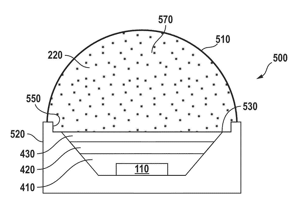
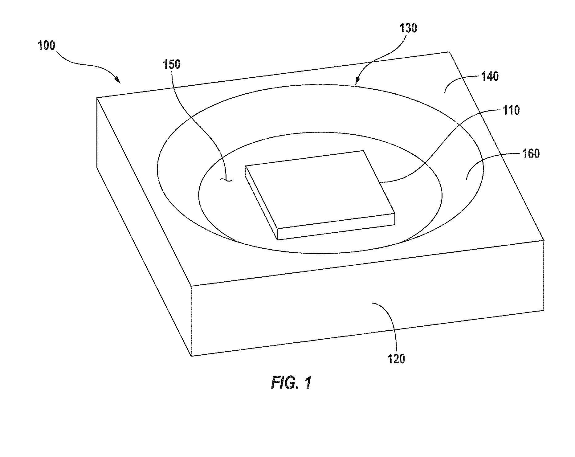
[0038]The present invention provides methods and devices for providing centered light output in a lighting apparatus. In some embodiments, improved total-internal-reflection lenses and / or LED packaging methods and materials are to produce centered light even when the light sources may be positioned off an optical axis.

[0039]In an embodiment, the present invention provides light-emitting devices that include a transparent matrix material encapsulating a light source. The light-emitting devices of the present invention can employ incandescent, sapphire crystal, fluorescent, or LED light sources that operate over the range of wavelengths from ultraviolet (UV) to Infrared (IR) which covers the range from about 200 to 2000 nanometers.

[0040]In one example, a light-emitting device includes a plurality of monochromatic LED elements configured to emit light of a plurality of colors. The transparent matrix material includes a dispersion of beads configured to scatter the light emitted by the ...


PUM


Abstract

A total-internal-reflection (TIR) lens for color mixing includes a body member having an outer surface and an interior open channel extending longitudinally through the body member. The body member and the interior open channel are substantially symmetric with respect to an optical axis, and the outer surface is shaped to provide total internal reflection. The body member has a first end surface region at a first end of the open channel for accommodating a light source and a second end surface region opposite the first end region. The second end surface region includes a plurality of refractive surface regions positioned around the second end region of the open channel. The lens is configured to provide projected light substantially centered with respect to the optical axis when the light source is positioned off the optical axis. In a specific embodiment, a lighting apparatus for providing centered white light includes such a lens and a plurality of light sources.

Description

CROSS-REFERENCES TO RELATED APPLICATIONS[0001]This application claims the benefit of U.S. Provisional Application Ser. No. 61 / 105,407, filed on Oct. 14, 2008 and entitled “TOTAL INTERNAL REFLECTION LENS FOR COLOR MIXING,” which is commonly owned and incorporated by reference herein.[0002]The application is also related to U.S. patent application Ser. No. 11 / 824,233, filed on Jun. 29, 2007 and entitled “MATRIX MATERIAL INCLUDING AN EMBEDDED DISPERSION OF BEADS FOR A LIGHT-EMITTING DEVICE,” which is commonly owned and incorporated by reference herein.BACKGROUND OF THE INVENTION[0003]The present invention relates generally to lighting apparatus and more particularly to methods and devices for providing centered light output. In some embodiments, improved total-internal-reflection lenses and / or LED packaging methods and materials are to produce centered light even when the light sources may be positioned off an optical axis.[0004]A light-emitting device includes a light source and a pac...

Claims


Application Information

Patent Timeline
IPC IPC(8): F21V5/04G02B3/00
CPCF21K9/00F21V5/04F21Y2101/02F21Y2113/007G02B19/0066G02B19/0028H01L33/58F21K9/64F21Y2115/10F21Y2113/17
Inventor JIANG, WUYAN, XIANTAOMEI, ZEQUN
Owner LEDENGIN
Learn More