Meal dryer/cooler

a technology of meal dryer and cooler, which is applied in the direction of drying machines, lighting and heating apparatus, and combination processes to achieve the effects of reducing the moisture content of meal, high electrical power demand, and thermal efficiency

Inactive Publication Date: 2010-04-15
DESMET BALLESTRA NORTH AMERICA INC
View PDF8 Cites 4 Cited by
  • Summary
  • Abstract
  • Description
  • Claims
  • Application Information

AI Technical Summary

Benefits of technology

[0007]Since the DC utilizes the heat of the meal as its major source of energy for reducing the meal moisture, it uses a minimum of steam and therefore has been seen as very thermally efficient. On the contrary, the fans required to push the air through the DC require a high electrical power demand. The basis of this invention was to modify the traditional DC in such a way as to maintain the thermal efficiency while simultaneously reducing the electrical power consumption of the fans.
[0008]The volumetric flow of air through the meal inside the DC must be maintained to insure adequate meal drying and cooling. Therefore, the key to reducing the fan electrical energy is through reducing the collective pressure drop to push the required volume of air through the incoming ductwork, DC air trays, the meal supported above the DC air trays, the outgoing ductwork and the cyclonic dust collectors. In studying the cumulative pressure drop through the entire air flow path, it was observed that approximately fifty percent of the entire pressure drop through the air path was caused by the air passing through the plurality of small round apertures at the top surface of each air tray. Attempts were first made to increase the quantity of small round apertures to reduce the back pressure. While this was effective in reducing pressure drop, the reduced pressure inside the air trays allowed meal supported above to sift through the round apertures and into the air trays. Meal inside the air trays becomes extremely dry and represents a smoldering hazard. Therefore, a different more novel approach was discovered for reducing pressure drop through the air trays.
[0009]It was found through experimentation that slotted apertures could replace round apertures in the top surface of the air trays. If the slotted apertures are approximately 0.25 mm in width, they have a sufficiently small enough width to allow the meal above to mechanically bridge the gap without sifting into the air tray. With this discovery, it was found that the total open area for air to pass through the air tray upper surface could be increased from approximately 0.8% up to approximately 2.0% without meal sifting into the tray. When the open area was nearly doubled, the pressure drop to push the air through the air tray was reduced by approximately half, and the total energy of the fan for the DC was reduced by approximately 25%.

Problems solved by technology

On the contrary, the fans required to push the air through the DC require a high electrical power demand.
Meal inside the air trays becomes extremely dry and represents a smoldering hazard.

Method used


Image

  • Meal dryer/cooler
  • Meal dryer/cooler
  • Meal dryer/cooler

Examples


Embodiment Construction

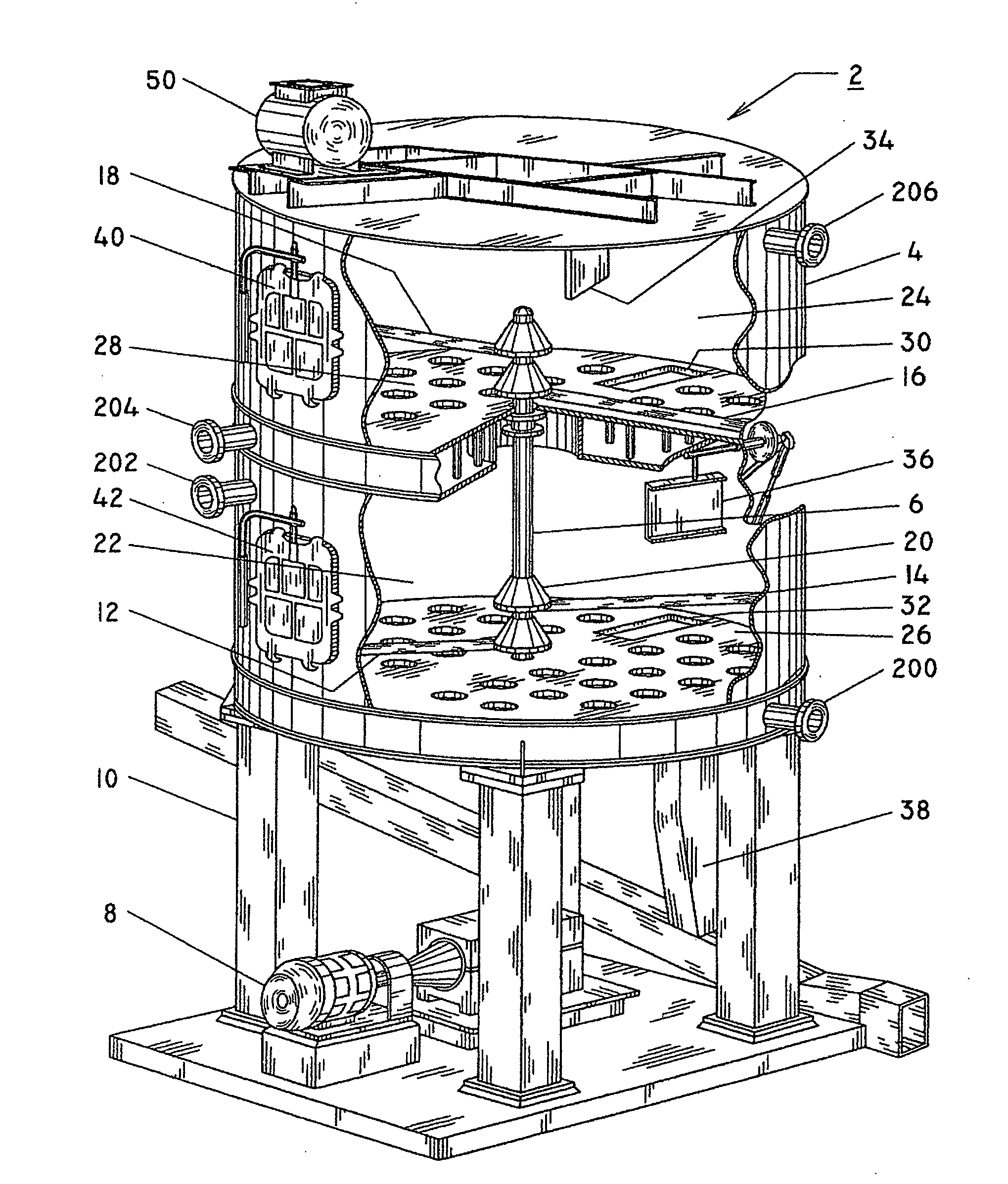
[0015]Turning first to FIG. 1, there is shown a meal dryer / cooler 2 in accordance with the invention. The meal dryer / cooler comprises a generally cylindrical housing 4 with a vertical shaft 6 extending through most of the housing and being generally coaxial therewith. The shaft is rotated by means of a motor 8 coupled thereto via conventional speed reducers, couplings and bearing members.

[0016]The assembly is supported by a plurality of supports 10. The vertical shaft 6 comprises a plurality of hub members 20 that carry radially extending stirrer arms 12, 14, 16, 18 which aid in stirring and moving the meal around the surface of the trays. As shown, a cooling zone or chamber 22 is provided between the trays 26 and 28 with a drying chamber 24 being defined between the tray 28 and the top portion of housing 4. Discharge gates 30, 32 are provided through the trays and feed the meal material via gravity discharge therethrough from the drying chamber 24 into the cooling chamber 22. After...


PUM


Abstract

Dryer / cooler (2) for oil bearing vegetable matter meal is provided wherein the dryer / cooler (2) has a cooling zone (22) and a drying zone (24) separated by a double bottom air plenum (28). The first surface (100) of the air plenum comprises a plurality of countersink bores (102) each receiving a slotted disc member (104) therein to provide open communication between the air plenum (26, 28) and one of the cooling or drying zones (22, 24).

Description

CROSS REFERENCE TO RELATED APPLICATIONS[0001]This application claims the priority benefit of U.S. Provisional Patent Application Ser. No. 60 / 906,980 filed Mar. 14, 2007 and of U.S. Provisional Patent Application Ser. No. 60 / 933,354 filed Jun. 6, 2007.FIELD OF THE INVENTION[0002]The invention pertains to an improved meal dryer / cooler.BACKGROUND OF THE INVENTION[0003]Oleagineous materials such as soybeans, rapeseed, sunflower seed, cottonseed, corn germ, etc. are prepared by thermal and mechanical means and then introduced into a solvent extractor wherein they are washed with hexane-based solvents to separate the liquid oil fraction from the solid meal fraction. The solid meal fraction discharges the extractor apparatus with approximately thirty percent by weight of residual solvent. The solid meal fraction is then introduced into a meal desolventizer toaster for the purpose of using steam, applied both indirectly and directly to the meal, to thermally remove the solvent. In the proce...

Claims


Application Information

Patent Timeline
Patent Type & Authority Applications(United States)
IPC IPC(8): F26B7/00F26B19/00
CPCF26B17/003
Inventor LOPEZ, FEDERICO
Owner DESMET BALLESTRA NORTH AMERICA INC
Why Eureka
Try Eureka