
Microwave lens

a micro-wave lens and lens technology, applied in the field of micro-wave lenses, can solve the problem of fixed resonance frequency of metamaterials and lens components, and achieve the effect of reducing the frequency of lens components

Inactive Publication Date: 2010-04-08
TOYOTA MOTOR CO LTD
View PDF11 Cites 8 Cited by
  • Summary
  • Abstract
  • Description
  • Claims
  • Application Information

AI Technical Summary

Benefits of technology

[0012]A microelectromechanical (MEMS) device is associated with at least one leg of at least one resonator cell in the array and, more typically, each resonator cell in the array includes at least one MEMS device. The MEMS device is movable between two p...

Problems solved by technology

One disadvantage of the previously known microwave lenses using metamaterials, however, is that the resonant frequency of the metamaterial, and thus of the lens, is fixed.

Method used


Image

  • Microwave lens
  • Microwave lens
  • Microwave lens

Examples


Embodiment Construction

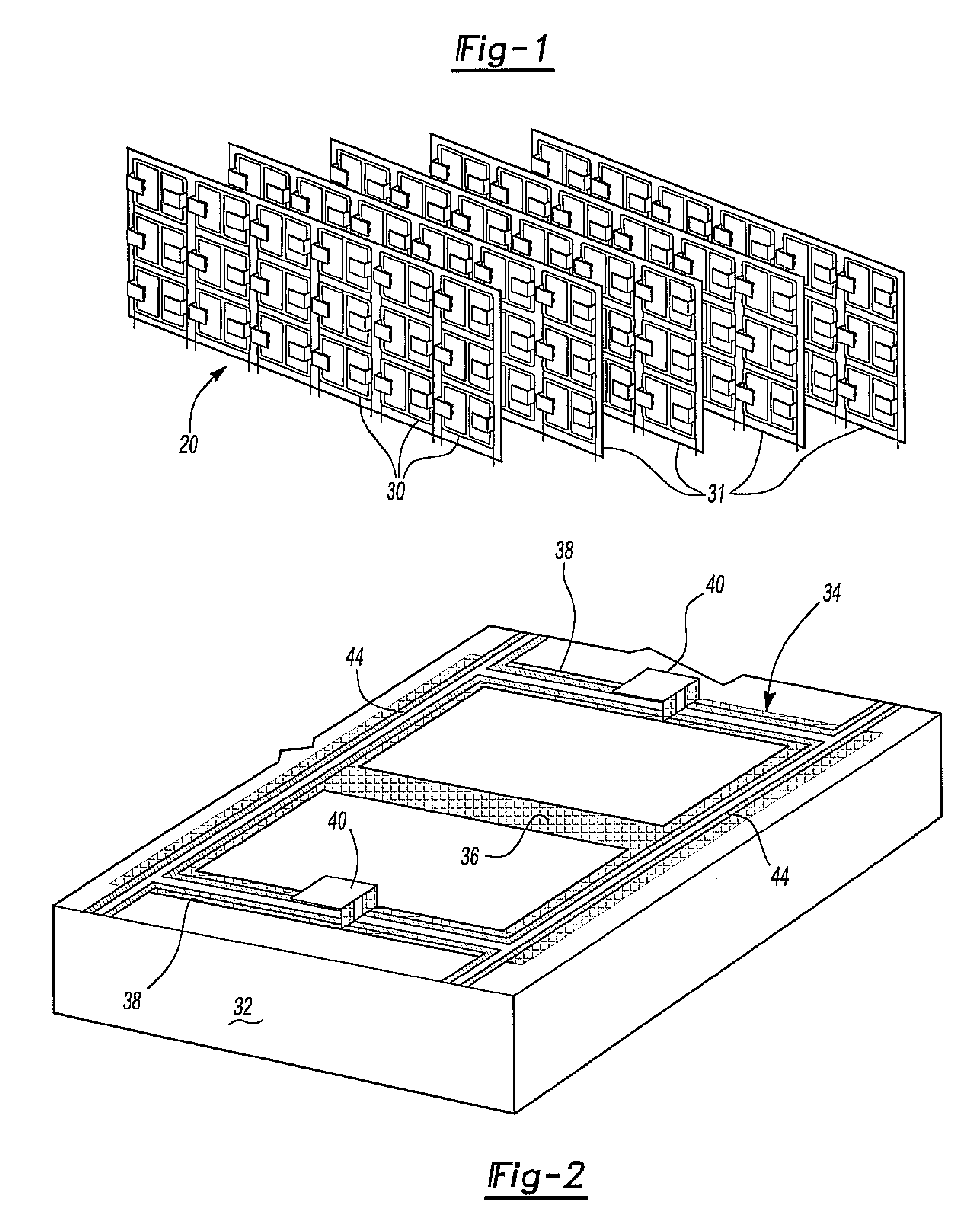
[0019]With reference first to FIG. 1, a microwave lens 20 is shown which comprises a plurality of electronic inductive capacitive (ELC) resonator cells 30. These cells are arranged in a planar array 32. Each array, furthermore, is illustrated in FIG. 1 as being rectangular in shape, although other shapes may be utilized without deviation from the spirit or scope of the invention.

[0020]Although a single planar array 32 may be used to form the microwave lens, more typically a plurality of planar arrays 32 are stacked on top of each other to form the lens.

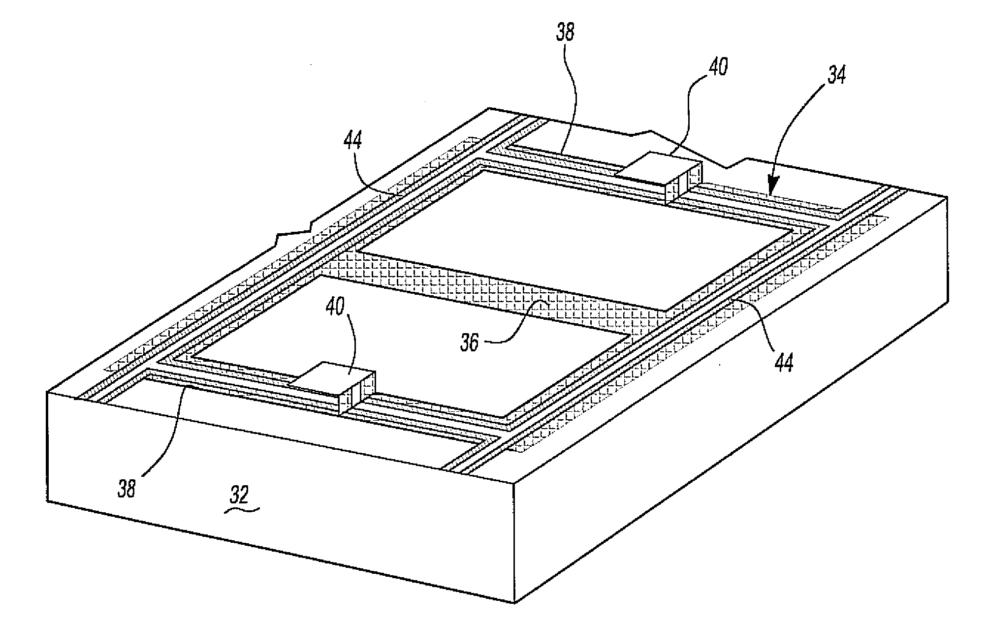
[0021]With reference now particularly to FIG. 2, a single resonator cell 30 is illustrated. The resonator cell 30 includes a substrate 32 made of an electrical insulating material. A conductive pattern 34 is then formed on the substrate 32 using conventional manufacturing techniques.

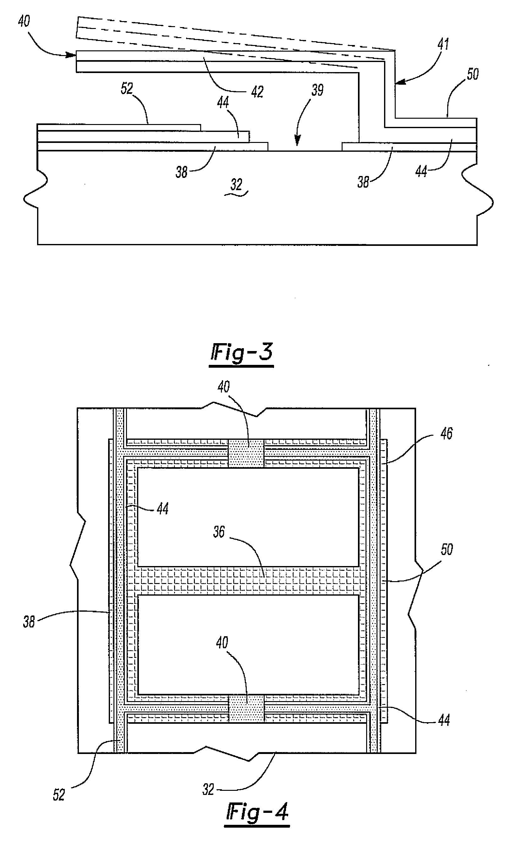
[0022]The pattern 34 includes a central leg 36 and two side legs 38 which are spaced apart and generally parallel to each other. The pattern of the resona...


PUM


Abstract

A microwave lens having an array of electronic inductive capacitive cells wherein each cell includes an electrically conductive pattern which responds to incident microwave electromagnetic energy as an LC resonator. At least one of the cells includes at least one MEMS device which is movable in response to an electrical bias to thereby vary the resonant frequency of that cell. In order to bias the MEMS device, an electrical insulating layer extends along a portion of the pattern of the cell and to both sides of the MEMS device. An electrically conductive strip then extends over the insulating layer so that the conductive strip is electrically insulated from the pattern while electrically connected to the MEMS device.

Description

BACKGROUND OF THE INVENTION[0001]I. Field of the Invention[0002]The present invention relates generally to microwave lenses and, more particularly, to a microwave lens constructed of a metamaterial and with a MEMS device to vary the resonant frequency of the lens.[0003]II. Description of Related Art[0004]The use of metamaterial in microwave applications, such as automotive radar systems, continues to expand. Such metamaterials exhibit properties in response to incident electromagnetic radiation which vary as a function of the shape of the metamaterial rather than the composition of the metamaterial.[0005]Conventionally, the metamaterial comprises a plurality of inductor-capacitor (LC) cells that are arranged in an array. Often the array is planar and a plurality of arrays are stacked one upon each other to form the microwave lens.[0006]Each cell in the array forms an LC resonator which resonates in response to incident electromagnetic radiation at frequencies which vary as a functio...

Claims


Application Information

Patent Timeline
IPC IPC(8): H03J3/20
CPCH01Q3/46H03J2200/19H03J3/20
Inventor LEE, JAE SEUNGYONAK, SERDAR H.
Owner TOYOTA MOTOR CO LTD
Learn More