
Framing system of studs and rails connected together by adapter members

a technology of adapter members and framing systems, applied in building reinforcements, walls, constructions, etc., can solve the problems of local creep, limited tolerances, and limited connection strength

Inactive Publication Date: 2010-04-08
KINGSPAN HLDG (IRL) LTD
View PDF8 Cites 21 Cited by
  • Summary
  • Abstract
  • Description
  • Claims
  • Application Information

AI Technical Summary

Benefits of technology

[0003]In one current arrangement the stud is located in the track and then fastened in place through the flanges. This provides a simple, site fixable method of construction. However, in use the stud usually sits on the internal radii of the track. Consequently, the connection relies on the restricted shear strength of the fastener. Tolerances are limited by site workmanship and varying settlement can present problems. As the frames are not assembled in a controlled environment, the positions of each fastener may not be exactly in line. Consequently, creep may occur locally in some studs when a load is applied to the frame.
[0005]The most structurally efficient of these systems facilitates end bearing of the stud into the web of the track. The use of external clamping mechanisms or specialist equipment however leads to high cost and complexity.

Problems solved by technology

Consequently, the connection relies on the restricted shear strength of the fastener.
Tolerances are limited by site workmanship and varying settlement can present problems.
Consequently, creep may occur locally in some studs when a load is applied to the frame.
This system is impractical because it is slow and difficult to operate and is inflexible.
The use of external clamping mechanisms or specialist equipment however leads to high cost and complexity.

Method used


Image

  • Framing system of studs and rails connected together by  adapter members
  • Framing system of studs and rails connected together by  adapter members
  • Framing system of studs and rails connected together by  adapter members

Examples


Embodiment Construction

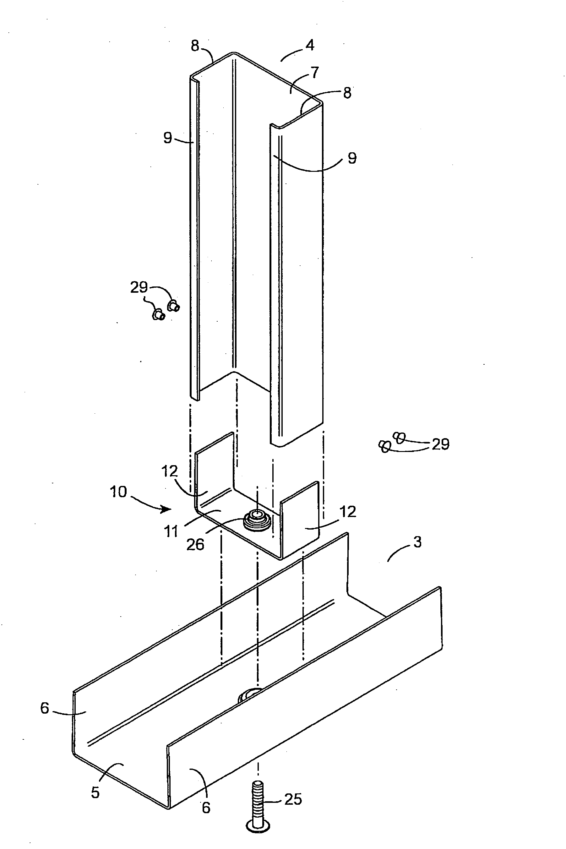
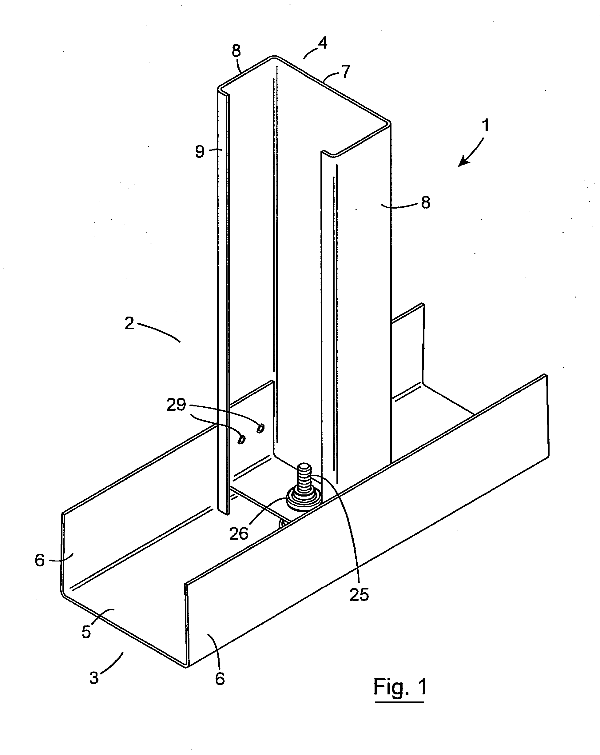
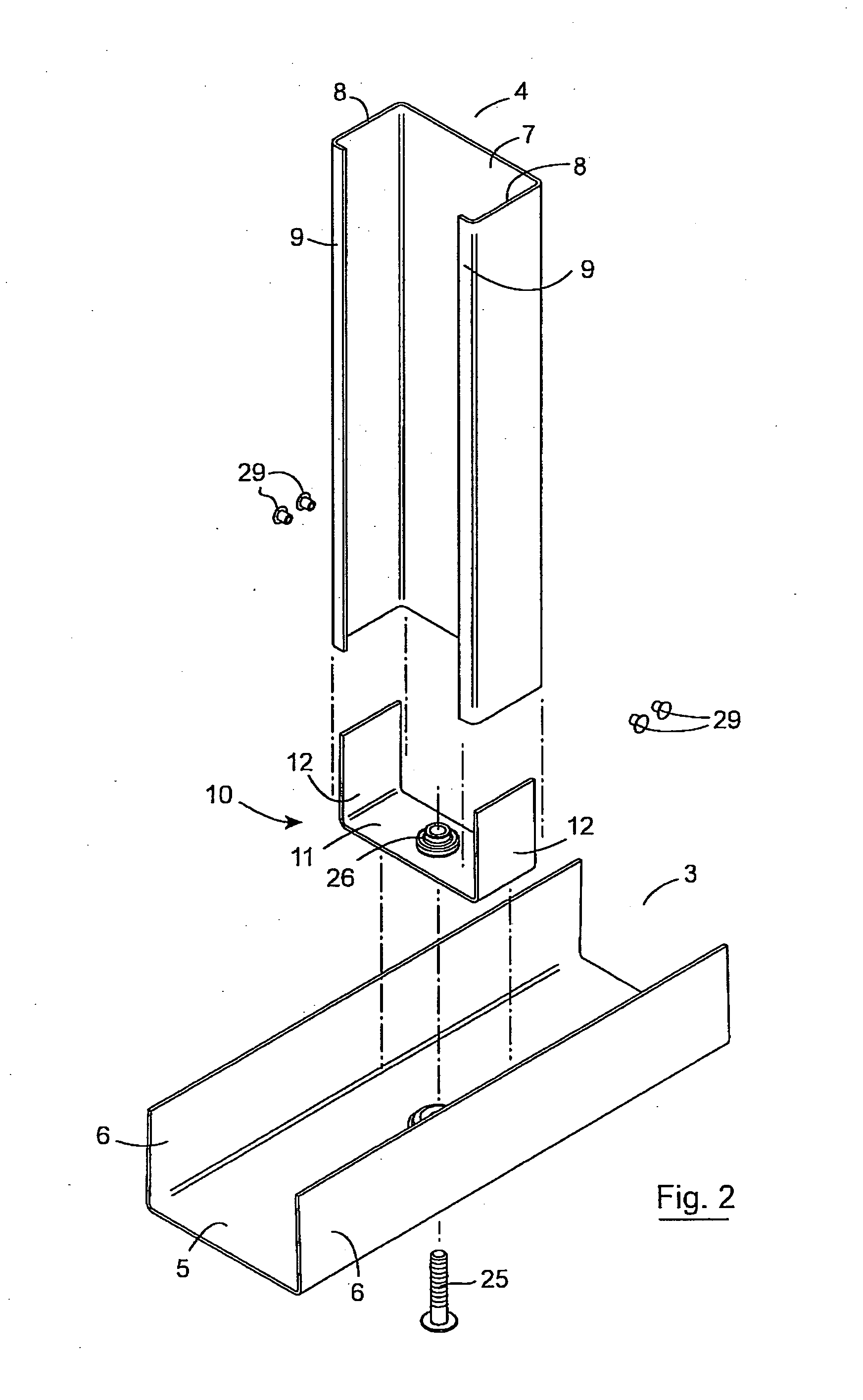
[0046]Referring to the drawings there is illustrated a structural framing system 1 according to the invention comprising a number of frame elements typically of metal, in this case steel sections, connected at joints 2. The frame elements in this case comprise track frame elements 3 and stud frame elements 4 which are interconnected to form the framing system.

[0047]The track frame element 3 is of rolled steel and comprises an elongated channel having a web 5, and side flanges 6 which extend continuously the length of the element 3. In this case the side flanges 6 are overbent. The overbent flanges 6 taper inwardly to the width of the stud to ensure a smooth joint between the stud and track frame elements.

[0048]The stud frame element 4 is also of rolled steel and comprises an elongated generally c-shaped lipped channel having a web 7, and side flanges 8 which extend continuously the length of the element. The side flanges 8 have inturned side lips 9.

[0049]The framing system comprises...


PUM


Abstract

A framing system (1) comprises track frame elements (3) and stud frame elements (4) which are interconnected at joints (2). The framing system comprises connection means for interconnecting the frame elements (3, 4) on assembly. The connection means comprises an adaptor (10) for a frame element and fixing means for fixing the adaptor to the frame elements. The adaptor conforms to at least part of the profile of at least one of the frame elements. In one case the adaptor (10) is of generally channel profile comprising a web (11) and side flanges (12). The side flanges of the adaptor (10) are engagable in the end of the stud frame element (4) such that the flanges (12) of the adaptor engage with the flanges (8) of the stud frame element (4). Rivets (30) are used to fix the stud frame element (4) to the adaptor (10). Track fixing means comprising a fixing bolt (25) extending to engage with a receiver (26) which is captive in the web (11) of the adaptor (10). The cross section of the stud frame element (4) has full bearing with the track frame element (3) for efficient load transfer.

Description

INTRODUCTION[0001]The invention relates to a structural framing system comprising a number of roll formed metal elements jointed together. Such a framing system may be used to provide a wall such as a partition wall of a building such as a modular building.[0002]Many framing systems of this type are known. Stud and track systems for structural applications must enable load transfer from the top track to the stud and from the stud to the bottom track. This must be achieved without short term settlement or long term creep.[0003]In one current arrangement the stud is located in the track and then fastened in place through the flanges. This provides a simple, site fixable method of construction. However, in use the stud usually sits on the internal radii of the track. Consequently, the connection relies on the restricted shear strength of the fastener. Tolerances are limited by site workmanship and varying settlement can present problems. As the frames are not assembled in a controlled ...

Claims


Application Information

Patent Timeline
IPC IPC(8): E04B2/76E04B2/60E04C5/12E04B1/24E04B1/58
CPCE04B1/24E04B2/766E04B2002/565E04B2001/2418E04B2001/2448E04B2001/2415E04B2/767
Inventor DAVIS, JEFF PAULBEREZANSKIJ, ANTONY
Owner KINGSPAN HLDG (IRL) LTD
Learn More