
Extended Private LAN

a private lan and extension technology, applied in the field of extended private lans, can solve the problems of time-consuming, time-consuming, and complicated process of creating and updating the topology of a vpn, and achieve the effect of reducing the complexity of the process, generating a significant amount of telemetry, and reducing the cost of a vpn

Inactive Publication Date: 2010-04-01
RPX CLEARINGHOUSE
View PDF8 Cites 99 Cited by
  • Summary
  • Abstract
  • Description
  • Claims
  • Application Information

AI Technical Summary

Benefits of technology

"The patent describes a network that allows a private LAN to connect to a roaming device, creating an Extended Private LAN. The network uses a control plane and a data plane to route traffic. The roaming device is authenticated and advertised into the network using an I-SID. The network can scale to support a large number of virtual private networks and allows for real-time or near-real-time addition of roaming devices. The network also provides Layer 2 connectivity for Ethernet \"plug and play\" behavior between devices on the private LAN and any roaming device. The invention can be implemented in software or hardware and can be delivered as a computer program product or downloaded to a network node."

Problems solved by technology

One of the difficulties of VPLS is that when a new end point connects to the network, there is a discovery process to discover all the other end points associated with the Virtual Private LAN service, followed by signalling to set up a mesh of service-specific pseudo-wires to serve the new end point.
This can take some time to achieve, will have intermediate states where only partial connectivity is available, and will generate a significant amount of telemetry due to the inefficiency of utilizing an N-squared mesh.
The process of creating, and updating the topology of, a VPN is further complicated when it is necessary to support roaming communication users who can connect to various points in a provider network, with the connection points often being unknown in advance.
As noted above, existing VPN technologies are primarily aimed at the enterprise sector, and are typically considered too difficult, or inflexible, to be applied at a residential scale or with fulfillment times that render them undesirable for roaming users.

Method used


Image

  • Extended Private LAN
  • Extended Private LAN
  • Extended Private LAN

Examples


Embodiment Construction

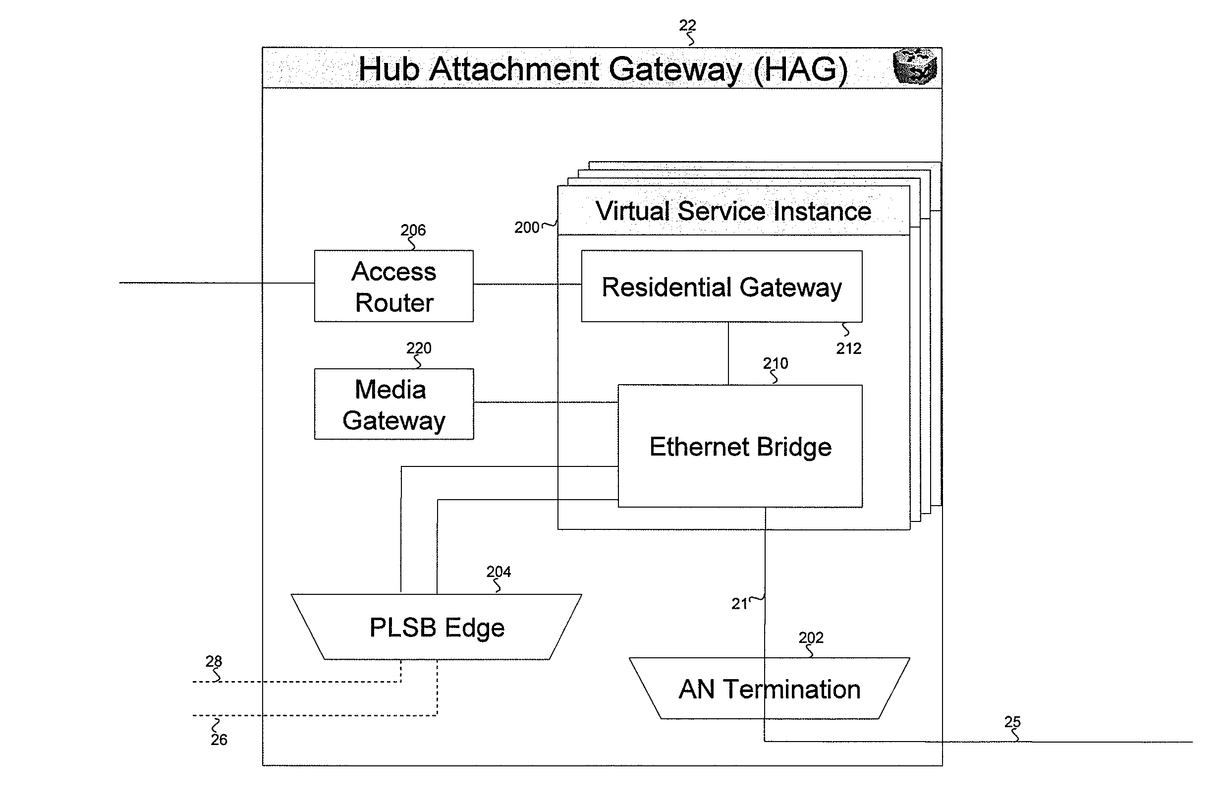
[0022]FIG. 1 shows a provider network 1 in accordance with an embodiment of the invention. The provider network 1 comprises a core network 40 and attachment networks 42, 44, 46. A communications subscriber has a private LAN network 10 at a premises 14, such as a home, office or other site. In a conventional manner, the private LAN network 10 comprises a wired or wireless Ethernet-based distribution network which connects devices 15. Devices 15 can include: a communication device; a server which stores music, video, digital images or any other form of media content; a broadcast receiver; a Personal Video Recorder (PVR); a printer; a home appliance; a security system; a home environment control system (e.g. controlling lighting, heating etc.) or any other device which is capable of being connected to the network.

[0023]In embodiments of the invention, an Extended Private LAN service is provided which has the effect of extending the private LAN 10 across the provider network 1 to roamin...


PUM


Abstract

A virtual private network is provided across a Provider Link State Bridging (PLSB) network between a first node connected to a private LAN and a second node connected to a roaming device. The roaming device is authenticated. A successful authentication results in a Service Identifier for the VPN being sent to the second node. Connectivity between members of the VPN service instance is maintained as part of the PLSB Link State process for forwarding table maintenance, rather than by any form of explicit signalling. A single Customer Virtual Bridge / Virtual Switch Instance can be located at the first node to provide point-to-point connectivity to each roaming device. A virtual Residential Gateway function can be combined with the Customer Virtual Bridge / Virtual Switch Instance.

Description

FIELD OF THE INVENTION[0001]This invention relates to providing a virtual private network across a provider network.BACKGROUND TO THE INVENTION[0002]Various forms of Virtual Private Networking (VPN) technologies allow a private network to be formed between geographically separate sites, using the resources of a provider network. Existing VPN technologies are primarily aimed at the enterprise sector, and connect sites of an enterprise. In addition they may allow home workers to access the network of their employer from their home office, or allow “road warriors” to access the network of their employer while travelling. A VPN can be established at networking Layer 2 or Layer 3.[0003]One type of existing Layer 2 VPN technology is the Virtual Private LAN Service (VPLS) over MPLS as described in the Internet Engineering Task Force (IETF) Requests for Comments (RFCs), numbers 4664, 4761 and 4762. This provides Ethernet multipoint-to-multipoint communication over IP / MPLS networks. Geograph...

Claims


Application Information

Patent Timeline
Patent Type & Authority Applications(United States)
IPC IPC(8): H04L12/28
CPCH04L12/4662
Inventor ALLAN, DAVIDCASEY, LIAM
Owner RPX CLEARINGHOUSE
Learn More