
Irrigation Nozzle Assembly with Fluidic insert Retention structure and method

a technology of retaining structure and nozzle, which is applied in the direction of lighting and heating apparatus, combustion types, manufacturing tools, etc., can solve the problems of compromised insert retention, and achieve the effect of convenient, reliable and inexpensiv

Inactive Publication Date: 2010-04-01
BOWLES FLUIDICS
View PDF1 Cites 18 Cited by
  • Summary
  • Abstract
  • Description
  • Claims
  • Application Information

AI Technical Summary

Benefits of technology

[0010]Accordingly, it is an object of the present invention to overcome the above mentioned difficulties by providing a convenient, reliable and inexpensive assembly structure and method for protecting a fluidic equipped irrigation nozzle from the water-hammer like effect of a first inrush of water.
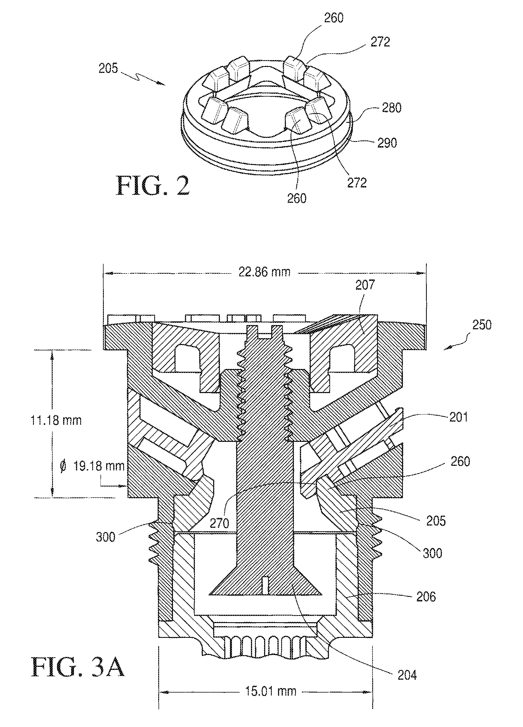
[0011]In accordance with the present invention, a sprinkler assembly includes a sprinkler housing including an interior lumen and an exterior sidewall, with at least one fluidic-circuit-receiving port carrying a fluidic insert configured that receives irrigation fluid passing into the housing lumen and, in cooperation with the port, passes irrigation fluid and projects the irrigation fluid in a desired spray pattern. The fluidic insert is held precisely in place by a retention ring adapted for insertion into the housing's interior lumen to provide a snap or friction fit with the housing. The retention ring fits into the pre-existing sprinkler housing or package, allows the use of plastic material and is made as a single component for economic purposes, and does not have any effect on external appearance or fluidic performance as other more traditional fasteners would. The retention ring can be customized to fit into other commercial sprinklers or Fluidic Nozzle housings.
[0012]The sprinkler assembly includes housing defining a cylindrical interior lumen or passage for irrigation fluid (e.g., water) and a latching retention ring is inserted into that lumen (pushed into the ID of the housing from underneath). Upon complete insertion, tab features mate to a “tail” on each fluidic insert that has been installed in the sprinkler assembly. The latch “tail” on the fluidic insert allows fluidic inserts to be assembled normally into the housing without any special tooling features or assembly processes (no snap action to overcome during assembly). The insert “tail” also has a web and gusset for additional strength. In order to accommodate the webbing on the insert “tail” there is a slot cut in each latch point on the retention ring. The latch point on the retention ring is widened to ensure that the proper level of shear area is retained for the stresses and strains the part is subjected to under the hydraulic surge's mechanical load (i.e., during surge).

Problems solved by technology

This is a critical aspect since applicants have found that if the ring is allowed to move, then insert retention is compromised.

Method used


Image

  • Irrigation Nozzle Assembly with Fluidic insert Retention structure and method
  • Irrigation Nozzle Assembly with Fluidic insert Retention structure and method
  • Irrigation Nozzle Assembly with Fluidic insert Retention structure and method

Examples


Embodiment Construction

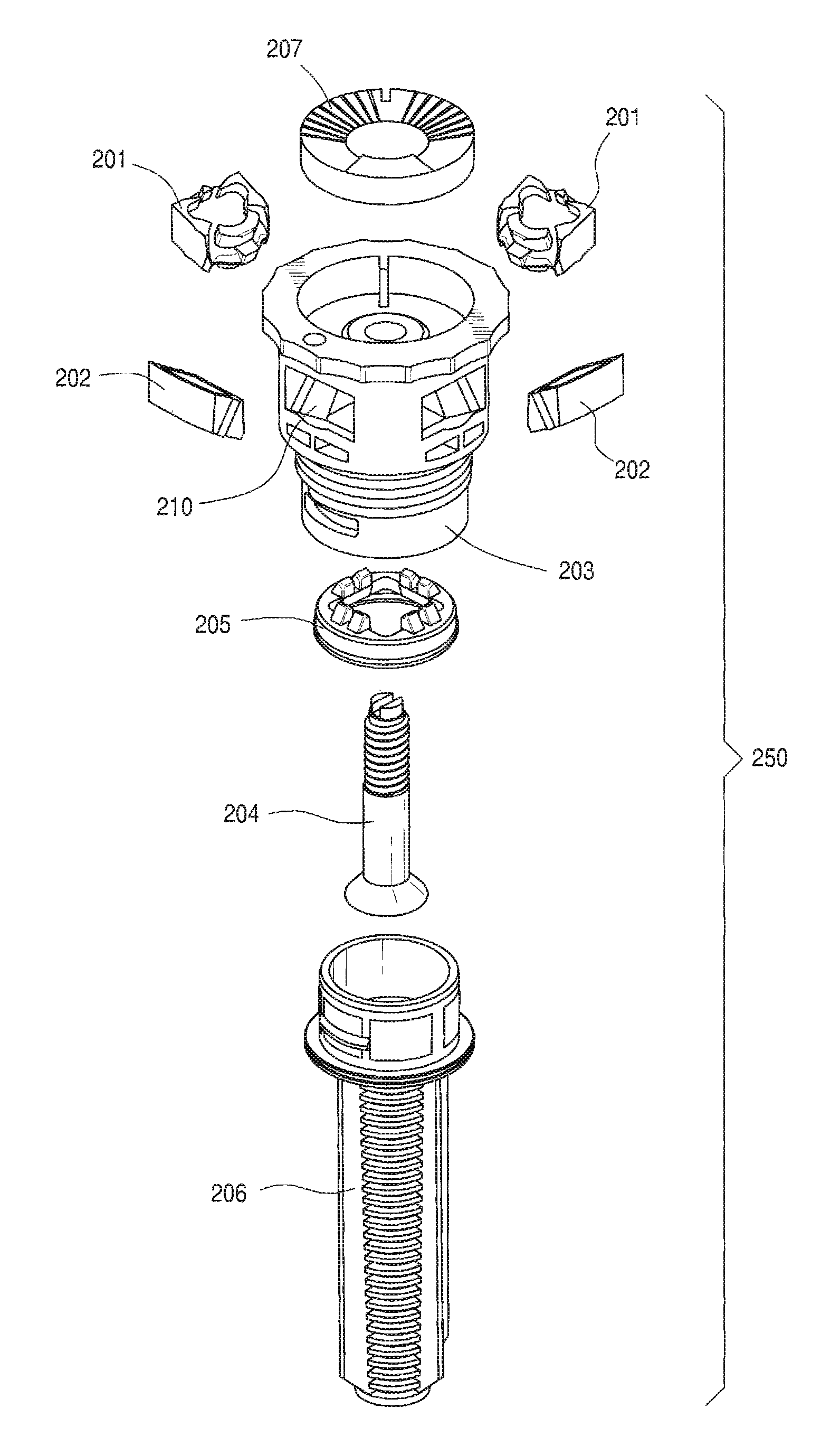
[0023]Turning now to FIGS. 1-5, in accordance with the present invention, an irrigation nozzle assembly 250 is illustrated in FIG. 1, which shows an exploded perspective view. Fluidic pop-up irrigation nozzle assembly 250 is adapted to receive from one to four fluidics 201 (i.e., chips or fluidic inserts) and from one to three blanks 202 in a housing 203 with four radially arrayed slots, a flow adjustment screw 204, and a ring-shaped retainer 205 which is configured to engage and retain the fluidic inserts.

[0024]In the illustrated embodiment, a long throw distance pop-up sprinkler head or irrigation nozzle assembly 250 achieves long throw distance using “fixed” components with no oscillating or rotating parts. While the illustrated embodiment is a “pop-up” sprinkler head adapted to function is an industry-standard form factor, other configurations are readily adapted from these examples. For example, the nozzle assembly 250 is readily altered to be “fixed”, and so need not include t...


PUM

PropertyMeasurementUnit
impact forceaaaaaaaaaa
diameteraaaaaaaaaa
axial lengthaaaaaaaaaa

Abstract

A sprinkler assembly includes a sprinkler housing including at least one fluidic- circuit-receiving port carrying a fluidic insert configured to receive irrigation fluid and project the irrigation fluid in a desired spray pattern. The fluidic insert is held precisely in place by a retention ring adapted for insertion into the housing's interior lumen to provide a snap or friction fit within the housing while engaging and retaining the fluidic insert against impact forces from inrushing fluid surge. The retention ring fits entirely within the sprinkler assembly's housing or package, and is economically molded as a one-piece component, and does not have any effect on external appearance of the sprinkler assembly or any adverse effect on the fluidic insert's spray pattern.

Description

PRIORITY CLAIMS AND REFERENCE TO RELATED APPLICATIONS[0001]This application claims priority to related and commonly owned U.S. provisional patent application No. 61 / 136,744, filed Sep. 30, 2009, the entire disclosure of which is incorporated herein by reference. This application is commonly owned with related U.S. patent application Ser. Nos. 61 / 012,200, 61 / 136,745 and 12 / 314,242 the entire disclosures of which are also incorporated herein by reference.BACKGROUND OF THE INVENTION[0002]1. Field of the Invention[0003]The present invention relates to irrigation nozzles, sprinkler heads and methods for assembling irrigation nozzles and sprinkler heads.[0004]2. Discussion of the Prior Art:[0005]Sprinkler systems used for irrigating lawns and parks must be serviced periodically, to prevent damage from expansion of freezing water in the pipes and sprinkler heads. Annually, the systems are cleared of water, often with compressed air, to drive all water out of the pipes and sprinkler compone...

Claims


Application Information

Patent Timeline
Patent Type & Authority Applications(United States)
IPC IPC(8): B05B1/00B23P11/00
CPCB05B1/08B05B1/14B05B1/304Y10T29/49826B05B15/065B05B15/10B05B15/008B05B15/40B05B15/74B05B15/65
Inventor SOUTH, CHRISRUSSELL, GREGORYGOPALAN, SHRIDHARHESTER, RUSSELLKOEHLER, ERIC
Owner BOWLES FLUIDICS
Learn More