
Method and device for producing an image of a thin layer of an object

a thin layer and object technology, applied in the field of producing an image of an object, can solve the problems of high adjustment requirements, significant limitations regarding the choice of wave length, and affecting the mapping of objects by artificial light, and achieve the effect of high quantitative precision of fluorescence measurements and sufficient in-depth selection

Inactive Publication Date: 2010-03-18
CARL ZEISS MEDITEC AG
View PDF10 Cites 22 Cited by
  • Summary
  • Abstract
  • Description
  • Claims
  • Application Information

AI Technical Summary

Benefits of technology

[0034]In order to increase the sensitivity in the layer and reduce the influences of artificial light, it is suggested, according to the invention, to use binary illuminating patterns as well as combine such areas in the detected images for correction of artificial light, which are within the light and dark areas of the illuminating patterns used for detecting images, and the edges of which exhibit a predetermined minimum distance from the transitions between the light and dark areas. This greatly reduces the influences of the transitions between light and dark areas and results, surprisingly, in a depth response function with a plateau near the maximum, providing for essentially constant sensitivity along the width of the plateau.
[0062]Therefore, the illuminating optical element of the device, according to the invention, should be designed as illumination lens with small aperture, whereby the optical axis of the illumination lens and the optical axis defined by the imaging optical element should form the angle α. This design provides for a large depth of field area. Preferably, the angle α should be greater than 50° in order to minimize the radiation intensity on the bottom of transparent objects or samples.

Problems solved by technology

However, artificial light can also compromise the mapping of the object because it decreases or alters the contrast of the detected intensity distribution.
However, compared to microscopes with wide field optical element, laser scanners exhibit a number of disadvantages.
Furthermore, there are significant limitations regarding the choice of wave length.
Additional disadvantages are many movable components, high adjustment requirements as well as low quantum efficiency of the detector, as a rule a photomultiplier.
This method is susceptible to artifacts when the grid does not produce sinusoidal illumination intensity on the sample.
In both cases, the calculations are relatively labor-intensive because trigonometric equations must be solved.
Therefore, the fluorescence intensity, caused by contamination of the reverse side, can be correspondingly high and lead to errors in measurements.
However, for the quantitative fluorescence microscopy, all aforementioned methods have the disadvantage that the precision of the concentration measurements of fluorescent material in the thin layer is still improvable, even though an in-depth selection is achievable and artificial light from the areas adjacent to the thin layer can be at least partially suppressed.

Method used


Image

  • Method and device for producing an image of a thin layer of an object
  • Method and device for producing an image of a thin layer of an object
  • Method and device for producing an image of a thin layer of an object

Examples


first embodiment

[0078]A device, shown greatly simplified and schematically in FIG. 1, for producing an image of a layer of an object, according to the invention, includes an illumination installation 1, an subsequent installation 2 for producing illuminating patterns in an object plane 3 of an object 4, arranged on a slide or stage, an imaging optical element 5 for mapping object 4 on an image plane B, as well as a resolving detector 6, arranged in the image plane. An evaluation installation 7 is connected to the detector 6 by means of a detector connection, and with installation 2 by means of a control line.

[0079]Illumination installation 1 contains a light or radiation source 8 with a subsequently arranged filter 9, a shutter 10 and, optionally, optical elements 11, which homogenize the optical path, and which, for example, can be a light transmission bar or a hollow rod with internal reflection; and furthermore, first illuminating optical elements 12 and 13 for homogenous illumination of an area...

second embodiment

[0133]The other steps are the same as in the first and

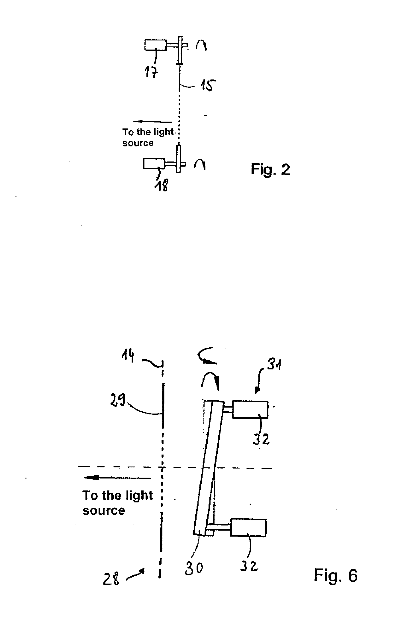
[0134]In a fifth embodiment of the method and the device, according to the invention, not the field stop 15 but the object 4 is moved. Thereto, a stage can be used, on which the object is arranged, and which is movable in directions parallel to the object plane 3 by means of a drive, controlled by the evaluation installation 7. The images are processed analogously to the first embodiment. For the positioning of the object 4 in the object plane 3, piezoactors, eccentric drives or other suitable adjustment mechanisms can be used, but preferably a motorized microscope stage. The second through the fourth embodiments can be modified accordingly.

[0135]A device, according to a sixth preferred embodiment of the invention, differs from the device of the first embodiment in such a way that a modified installation 28, shown in principle in FIG. 6, for producing illuminating patterns and an accordingly modified evaluation installation are u...


PUM


Abstract

A method for producing an image of a layer of an object by a wide field optical element on a resolving detector. The object is illuminated in a focused manner on at least one object plane having at least two binary illuminating patterns. The corresponding images are detected. Light and / or the dark areas of the illuminating patterns completely cover the object when the illuminating pattern is superimposed. A layer image determined from the detected images, includes a partial segment that respectively reproduces a partial area of the object that is arranged inside the light area of one of the used illuminating patterns. Edges are arranged at a distance from the edges of the light area about at least one predefined minimum distance.

Description

PRIORITY CLAIM[0001]The present application is a National Phase entry of PCT Application No. PCT / EP2007 / 005662, filed Jun. 27, 2007, which claims priority from German Application Number 102006031177.9, filed Jul. 6, 2006, the disclosures of which are hereby incorporated by reference herein in their entirety.FIELD OF THE INVENTION[0002]The invention relates to a method for producing an image of a thin layer of an object, particularly by means of a wide field optical element, as well as a respective device.BACKGROUND OF THE INVENTION[0003]Biological samples or materials are frequently examined microscopically. Particularly, appropriate objects can be examined for detection of structures with wide field optical elements, which show the object and / or a thin layer, ideally a plane, of said object on a resolving detector. Such imaging examination can be carried out, for example, with standard microscopy or fluorescence microscopy. The thin layer, for example, can be a fluorescent layer on...

Claims


Application Information

Patent Timeline
Patent Type & Authority Applications(United States)
IPC IPC(8): H04N7/18
CPCG02B21/06G02B21/367G02B21/16
Inventor WESTPHAL, PETERBUBLITZ, DANIEL
Owner CARL ZEISS MEDITEC AG
Learn More