Method and Apparatus for Tuning and Matching MRI/NMR Probe
- Summary
- Abstract
- Description
- Claims
- Application Information
AI Technical Summary
Benefits of technology
Problems solved by technology
Method used
Image
Examples
example 1
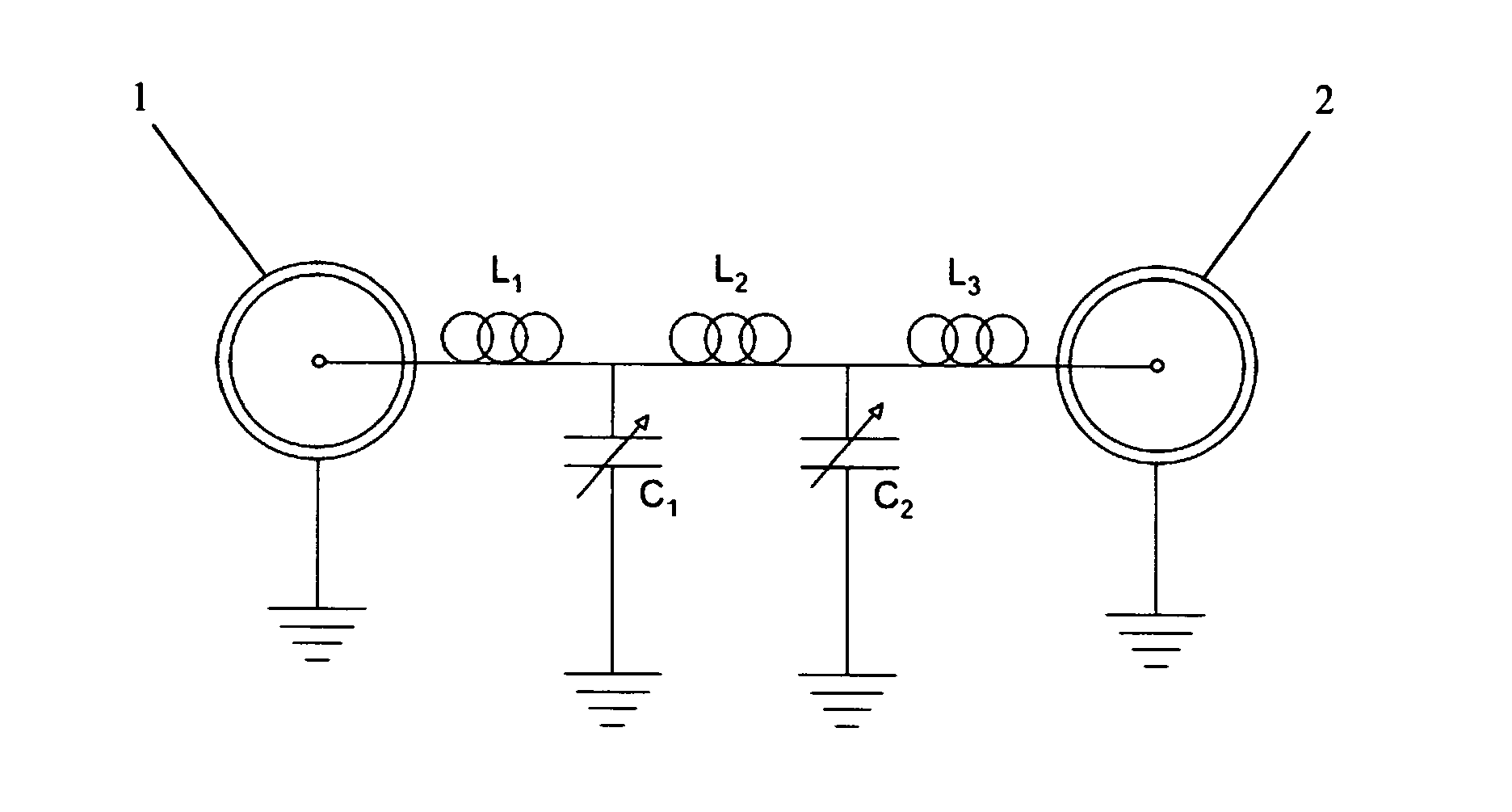
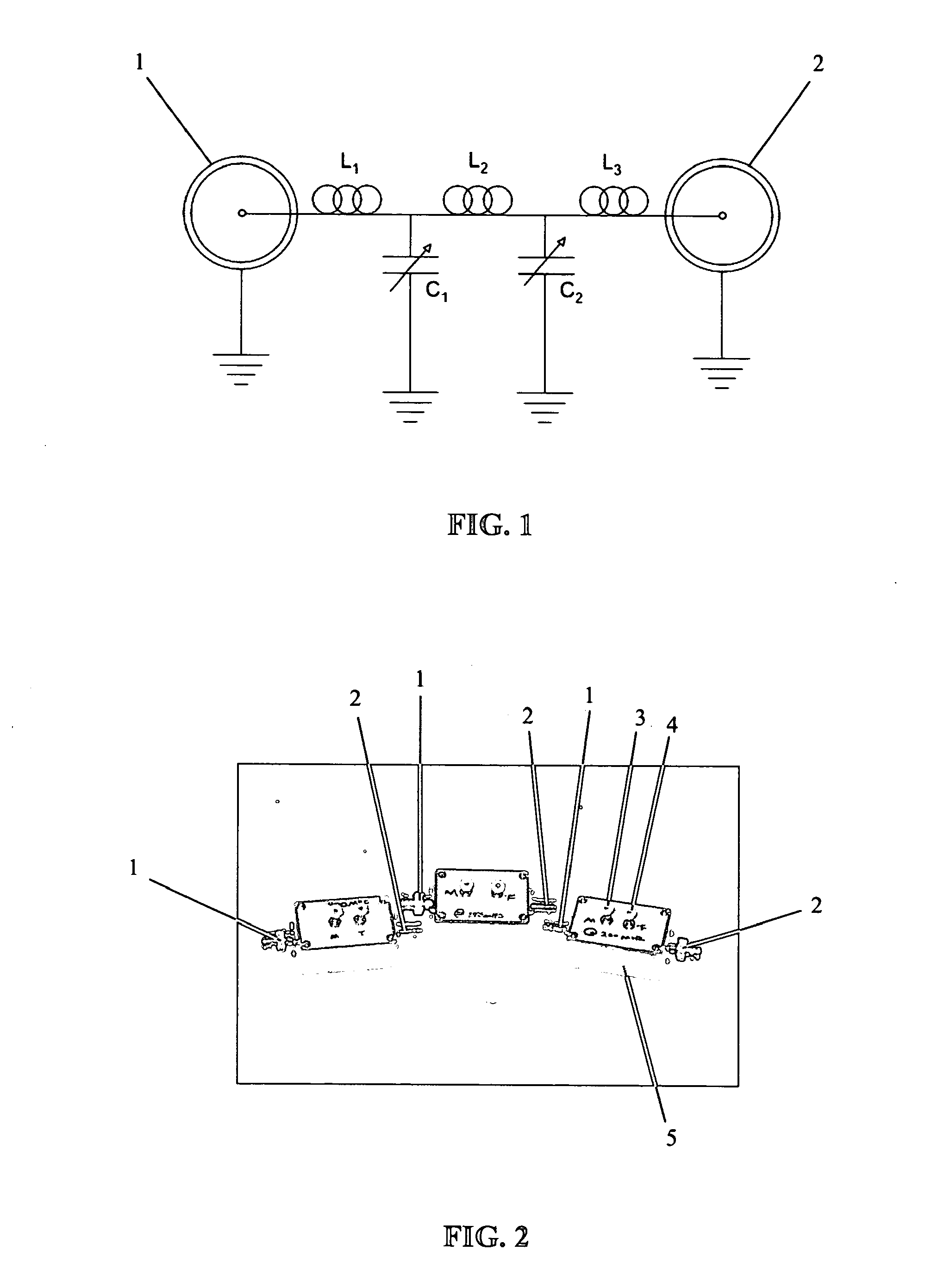
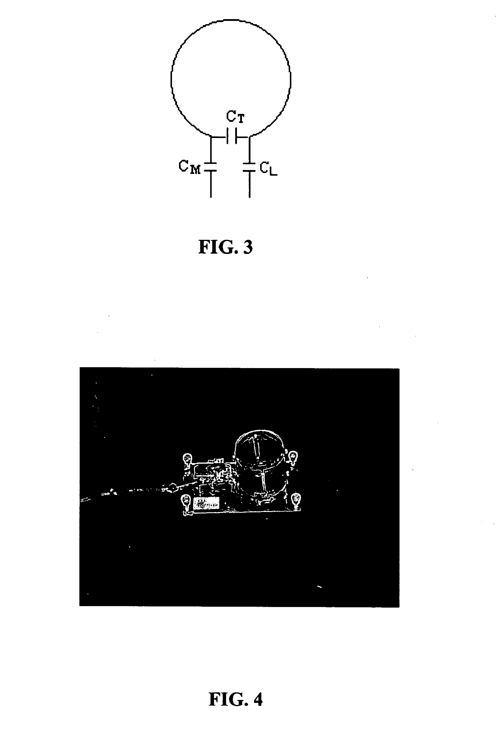
[0040]For this example, a loop gap coil (32×35 mm), such as shown in FIG. 4, was loaded with copper sulfate solution. It should be noted that the method described here can work with any RF coil. The probe was tuned using a HP8753E Network Analyzer and the effect of coupling with the magnet simulated using a copper clad cylinder. The coil is said to be unmatched when the matching capacitor has been adjusted until it exhibits a reactance other than 50 ohms impedance at the end of the transmission line. This results in a low value, such as less than −4 db, of return loss (S11) tuning dip observed on the network analyzer. The properly matched and tuned circuit has approximately a −35 db return loss dip. The results were also compared with bench tests performed on the circuit using the HP 8753E Network Analyzer with port calibrations and the use of the Smith Chart functions. The M-T box circuit used in this example is shown in FIG. 1, and incorporates a symmetrical and balanced capacitan...
example 2
[0046]The development of the 900 MHz UWB magnet at the National High Magnetic Field Laboratory (NHMFL) generates significant challenges in RF engineering. The construction of relatively large volume coils at such high frequencies provides challenges in terms of tuning and matching, loading, RF inhomogeneities and wave effects, and the tight spatial constraints in in vivo studies looking to maximize the full use of the magnet bore. The increased length of the magnet and hence the RF probe also provides non-trivial issues for remote tuning and matching, sample maintenance in in vivo studies, and SNR maximization.
[0047]In this example, a single tuned birdcage coil at 900 MHz is described, incorporating an embodiment of the subject remote tuning device. These coils fit in the conventional wide bore gradients of the 900 MHz system. FIG. 5 shows a 900 MHz probe body (on right) next to a 750 MHz probe body (on left).
[0048]A conventional birdcage coil, as shown in FIG. 6, was constructed to...
PUM
 Abstract
Description
Claims
Application Information
 - R&D
- Intellectual Property
- Life Sciences
- Materials
- Tech Scout
- Unparalleled Data Quality
- Higher Quality Content
- 60% Fewer Hallucinations
Browse by: Latest US Patents, China's latest patents, Technical Efficacy Thesaurus, Application Domain, Technology Topic, Popular Technical Reports.
© 2025 PatSnap. All rights reserved.Legal|Privacy policy|Modern Slavery Act Transparency Statement|Sitemap|About US| Contact US: help@patsnap.com


