
Thermal spraying apparatus

a spraying apparatus and spraying technology, applied in the direction of movable spraying apparatus, coating, metal material coating process, etc., can solve the problems of inability to completely prevent the adhesion of spray fumes to an unsprayed surface of a bore surface, not going so far as to prevent the adhesion of spray fumes and the like, and achieve high bond strength, improve the durability of the cylinder block, and improve the effect of durability

Inactive Publication Date: 2010-03-18
TOYOTA JIDOSHA KK
View PDF7 Cites 15 Cited by
  • Summary
  • Abstract
  • Description
  • Claims
  • Application Information

AI Technical Summary

Benefits of technology

[0012]According to the thermal spraying method of Patent Document 2, the operation of attaching / detaching a masking member can be eliminated. However, it merely adjusts the spray angle. With this configuration, the adhesion of reflected particles and spray fumes to an unsprayed surface of a bore surface cannot be prevented completely. In addition, according to the thermal spraying method of Patent Document 3, although fumes adhered to a bore surface may be removed, it does not go so far as to prevent the adhesion of fumes and the like.
[0013]The present invention is made in view of the problems mentioned above. Its object is to provide a thermal spraying apparatus that is capable of, with a simple apparatus configuration, effectively preventing the adhesion of reflected particles and spray fumes to a cylinder bore surface during spraying.

Problems solved by technology

With this configuration, the adhesion of reflected particles and spray fumes to an unsprayed surface of a bore surface cannot be prevented completely.
In addition, according to the thermal spraying method of Patent Document 3, although fumes adhered to a bore surface may be removed, it does not go so far as to prevent the adhesion of fumes and the like.

Method used


Image

  • Thermal spraying apparatus
  • Thermal spraying apparatus
  • Thermal spraying apparatus

Examples


Embodiment Construction

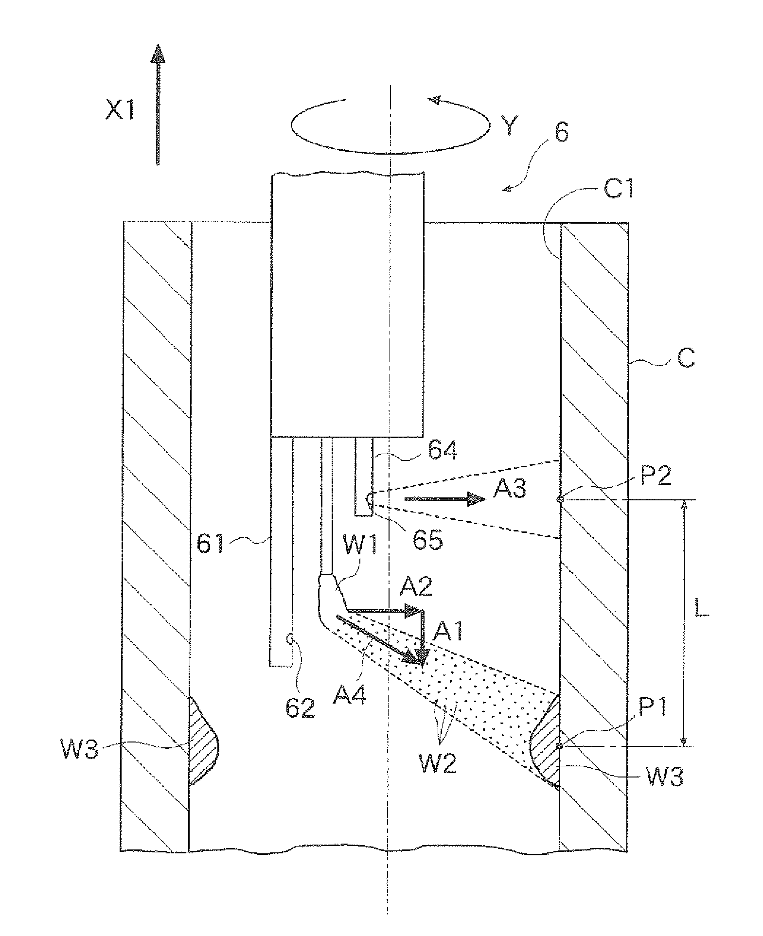
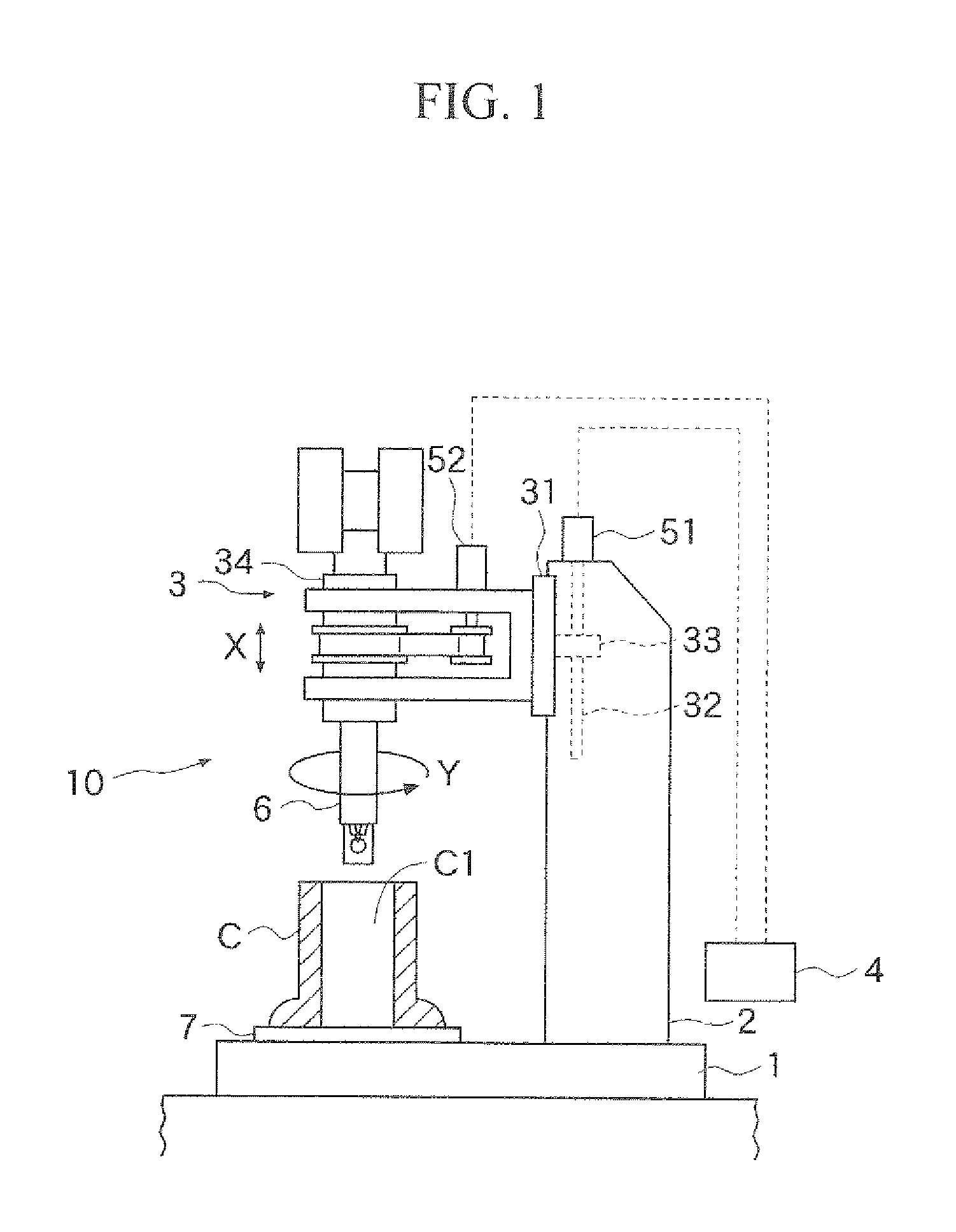
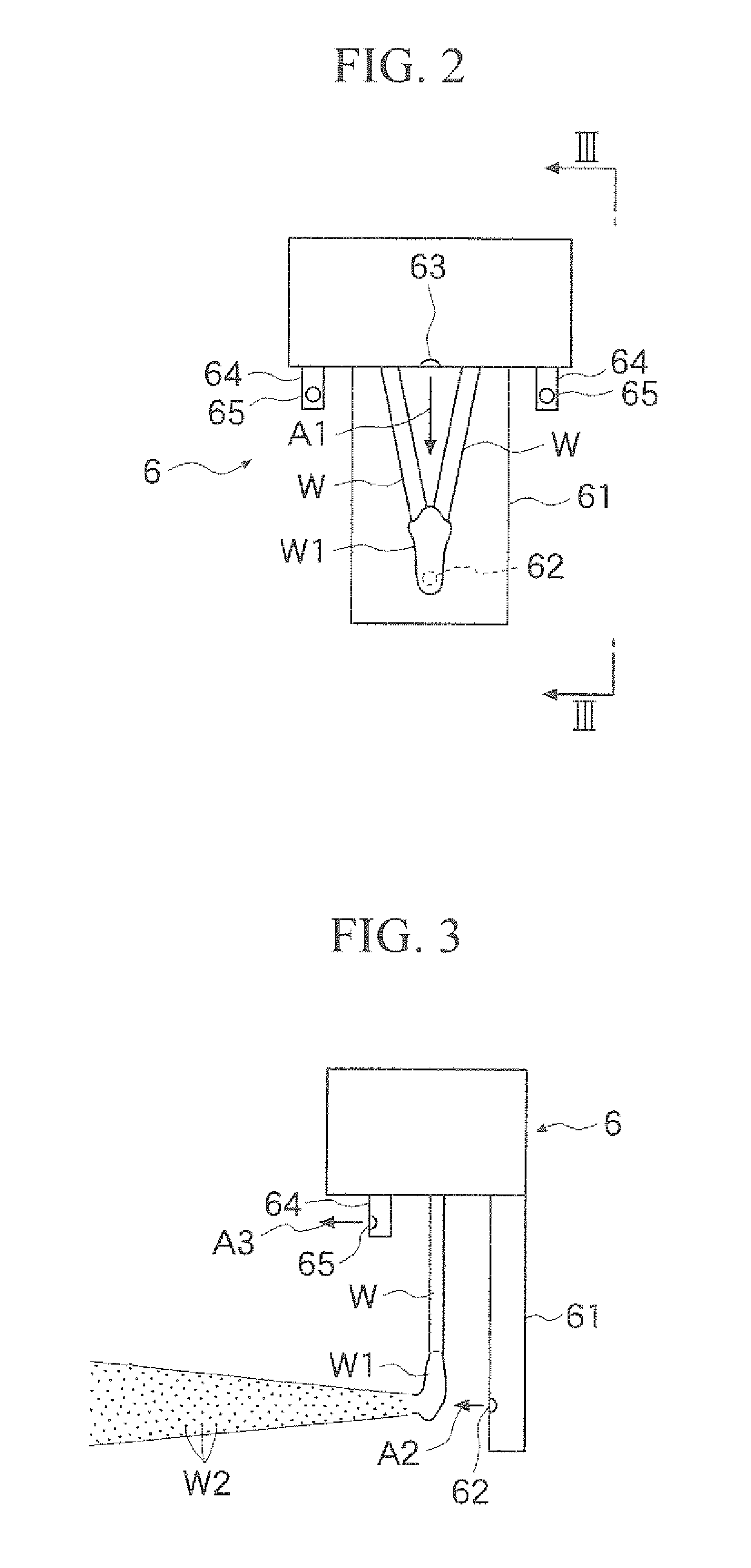
[0036]An embodiment of the present invention is described below with reference to the drawings. FIG. 1 is a schematic. view showing a thermal spraying apparatus of the present invention. FIG. 2 is an enlarged view of a spray gun. FIG. 3 is a view of FIG. 2 in the direction of arrow III-III. FIG. 4 is a view illustrating a state in which a spray gun is spraying spray particles onto a cylinder bore surface, and is also a view illustrating the region, where the axial center of a third discharge opening intersects the bore surface, and a deposition center of the spray particles. FIG. 5 is a graph showing experiment results relating to the distance between the region, where the axial center line of a third discharge opening intersects the bore surface, and a deposition center of the spray particles, and to the bond strength of the spray coating above the deposition center. FIG. 6 is optical microscope images of cross sections of the boundary between a bore surface and a spray coating.

[00...


PUM

PropertyMeasurementUnit
inner diameteraaaaaaaaaa
pressureaaaaaaaaaa
pull-up speedaaaaaaaaaa

Abstract

A thermal spraying apparatus that is capable of effectively preventing the adhesion of spray fumes to unsprayed regions of a bore surface during arc spraying is provided. To this end, a thermal spraying apparatus 10 comprises a spray gun 6 that moves within a cylinder bore. The spray gun 6 has at one end thereof a first discharge opening (atomizing nozzle 62) that faces a direction that is orthogonal to the movement direction, has a second discharge opening (auxiliary nozzle 63) that faces a direction that is orthogonal to the nozzle 62, and has, at a predetermined region located further to the side in the movement direction of the spray gun 6 than the nozzle 62, third discharge openings (fume adhesion prevention nozzles 65) for discharging a fluid and that faces the same direction as the nozzle 62. A droplet, which forms as an arc spray wire material melts at the tip of the spray gun 6, is stretched with auxiliary air A1. By blowing atomizing air A2 onto the droplet, spray particles are formed and sprayed onto the bore surface. At the same time, fume adhesion prevention air A3 is blown towards the cylinder bore surface in synchrony with the spraying of the spray particles.

Description

TECHNICAL FIELD[0001]The present invention relates to a thermal spraying apparatus that forms a spray coating on an inner circumferential surface of a cylinder bore of an engine and the like.BACKGROUND ART[0002]On cylinder bore surfaces of cylinder blocks, spray coatings for improving the corrosion resistance, wear resistance, and the like of the bore surfaces are formed by thermal spraying techniques in which a combustion flame is generated by an arc, plasma, gas, or the like, various metals or alloys are instantaneously melted, and spray particles which have been atomized (micro-particulated) by compressed air are made to impact / solidify and adhere. Such thermal spraying is performed by moving a spray gun in a rotating posture between both ends of a cylinder bore as disclosed in Patent Document 1, for example. However, when the spray particles impact the bore surface, spattering of the spray particles occurs, which causes such problems as the adhesion of these reflected particles ...

Claims


Application Information

Patent Timeline
Patent Type & Authority Applications(United States)
IPC IPC(8): B05B3/02
CPCB05B7/224C23C4/16C23C4/125B05B13/0627B05B7/0075B05B13/0636B05B12/18C23C4/131
Inventor KODAMA, KOTAMIYAMOTO, NORITAKA
Owner TOYOTA JIDOSHA KK
Learn More