
Overturning prevention device for forklift vehicle

a technology for preventing devices and forklifts, which is applied in the direction of steering initiations, instruments, vessel construction, etc., to achieve the effect of lowering the cargo height and high safety

Inactive Publication Date: 2010-03-11
MITSUBISHI HEAVY IND LTD
View PDF7 Cites 49 Cited by
  • Summary
  • Abstract
  • Description
  • Claims
  • Application Information

AI Technical Summary

Benefits of technology

[0030]According to the present invention as claimed in claim 1 through claim 4, warning is occurred in accordance with a vehicle velocity so that a forklift vehicle can be prevented from being overturned. Particularly, according to the present invention as claimed in claim 2, warning is occurred in multi-steps so that an operator can prevent the vehicle from being overturned sufficiently. According to the present invention as claimed in claim 3, warning is occurred in accordance with a presumption velocity after a predetermined period from the present time so that an operator can prevent the vehicle from being overturned sufficiently. According to the present invention as claimed in claim 4, one of deceleration of a vehicle, lowering a cargo height and a prohibit of increasing a steering rotational angle is operated after warning so that an operator is not surprised of a selected operation since the warning is already recognized by the operator.
[0033]According to the present invention as claimed in claim 17 through claim 20, an allowable acceleration at which with vehicle is not overturned toward a front-rear direction is presumed so that an overturning phenomenon can be avoided in the case that a vehicle drives rapidly. Particularly, according to the present invention as claimed in claim 19 and claim 20, an overturning prevention phenomenon towards not only the front-rear direction but also the lateral direction can be avoided so that the vehicle can be driven with high safety.

Problems solved by technology

However, the Patent Publication 1 does not disclose any other methods.

Method used


Image

  • Overturning prevention device for forklift vehicle
  • Overturning prevention device for forklift vehicle
  • Overturning prevention device for forklift vehicle

Examples


first embodiment

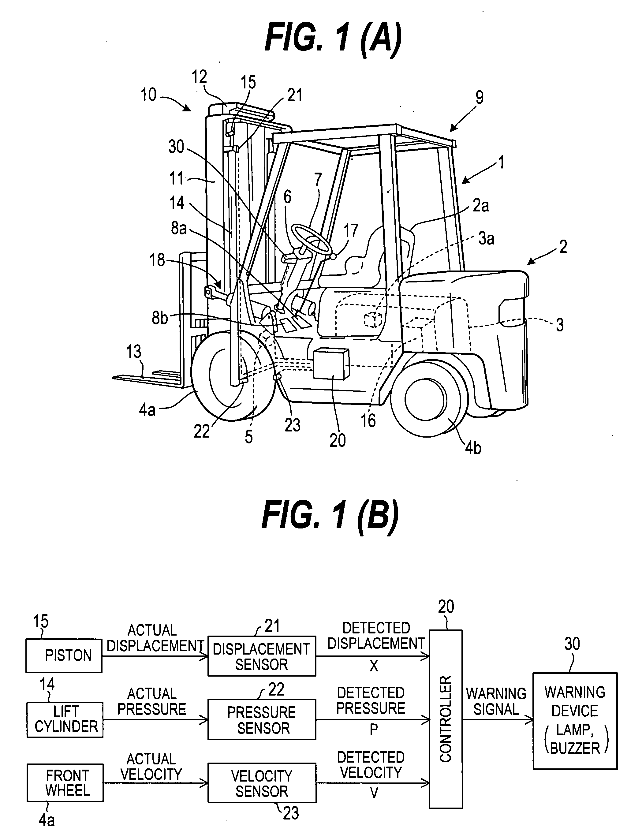
[0067]FIG. 1 explains the

[0068]At first, the whole structure of a forklift vehicle is explained. The forklift vehicle 1 comprises a vehicle body 2 in which a diesel type engine 3 as a driving device is installed. An output control device 3a is attached to the engine 3. Driving force of the driving device is transmitted to front wheels 4a through a gear mechanism (not shown). Rear wheels 4b are steered wheels so that driving force is not transmitted thereto. A braking device 5 is adapted for the front wheels.

[0069]An operator seat 2a is arranged at an upper middle portion of the vehicle body 2. A steering 7 attached to a steering support member 6 is provided in front of the operator seat 2a. An acceleration pedal 8a and a braking petal 8b are provided adjacent to a root portion of the steering support member 6. In order to protect an operator sitting on the operator seat 2a, a protective member 9 formed by four vertical support columns and an upper frame attached to each upper end of...

second embodiment

[0092]A hydraulic control device 16 for feeding hydraulic oil to a lift cylinder 14 has a relief valve 16c. FIG. 6 shows the hydraulic control device 16 and the relief valve 16c. The hydraulic control device comprises a pump 16a, a switch valve 16b connected to a lift lever. In addition, the second embodiment further comprises the relief valve 16c.

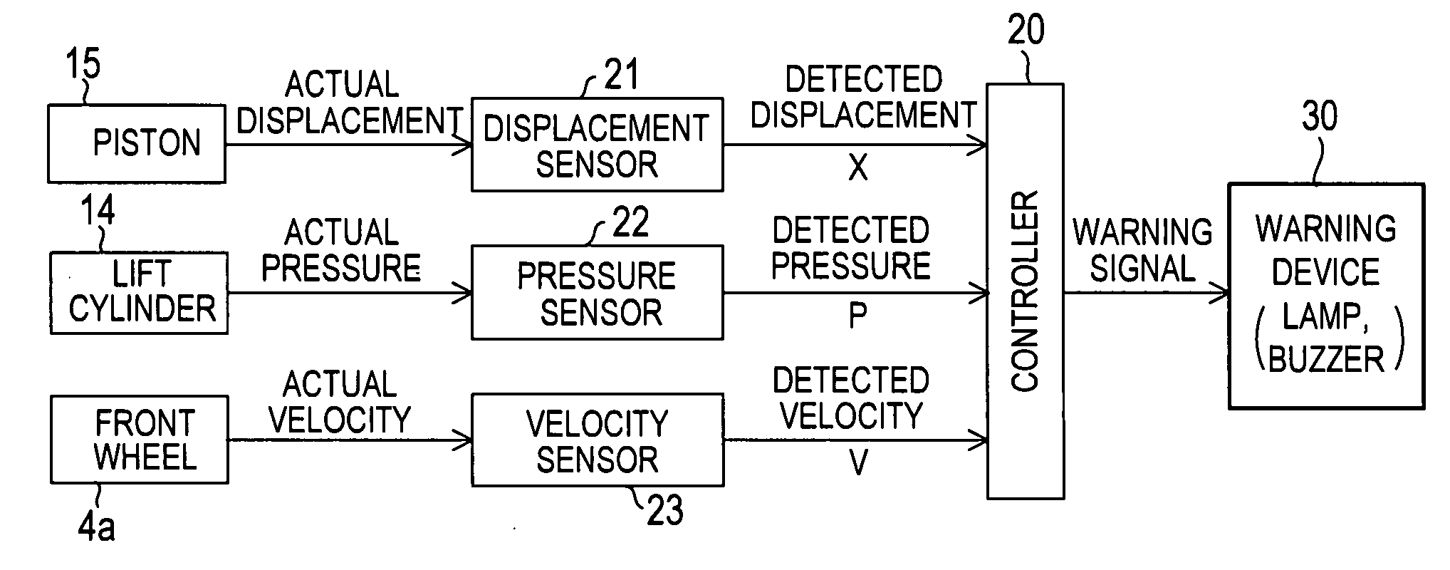
[0093]FIG. 5(B) explains signals transmitting to / receiving from tools in the second embodiment. As similar as the first embodiment, a displace amount of a piston 15 is detected by a displacement sensor 21 and the detected displacement X is transmitted to a controller 20. A pressure sensor 22 detects pressure applied to a lift cylinder and detected pressure P is transmitted to the controller 20. A velocity sensor 23 detects velocity (rotational velocity) of a front wheel 4a. The data of the detected velocity V is transmitted to the controller 20. In the second embodiment, the pedal sensor 24 detects the stepping amount As of the accelerati...

third embodiment

[0110]The third embodiment has the above structure and operated as described above. In order to prevent for the vehicle from being overturned, the braking device 5 is actuated so as to prevent the rolling moment from being greater than the limit moment M1.

[0111]In the next, the first modified example of the third embodiment will be described. The example comprises a steering resistant device 19 for controlling rotations of a steering 7. If the limit moment M1 is less than the rolling moment M2, the steering resistant device 19 controls the steering 7 not to increase a steering angle. FIG. 13(A) shows a structure of the first modified example of the third embodiment. Upon comparing with the third embodiment, it is only different that the steering resistant device 19 is provided. FIG. 13(B) explains signals transmitting to / received from the devices in the first modified example of the third embodiment.

[0112]FIG. 14 shows a model of a steering resistant device 19. The steering resistan...


PUM


Abstract

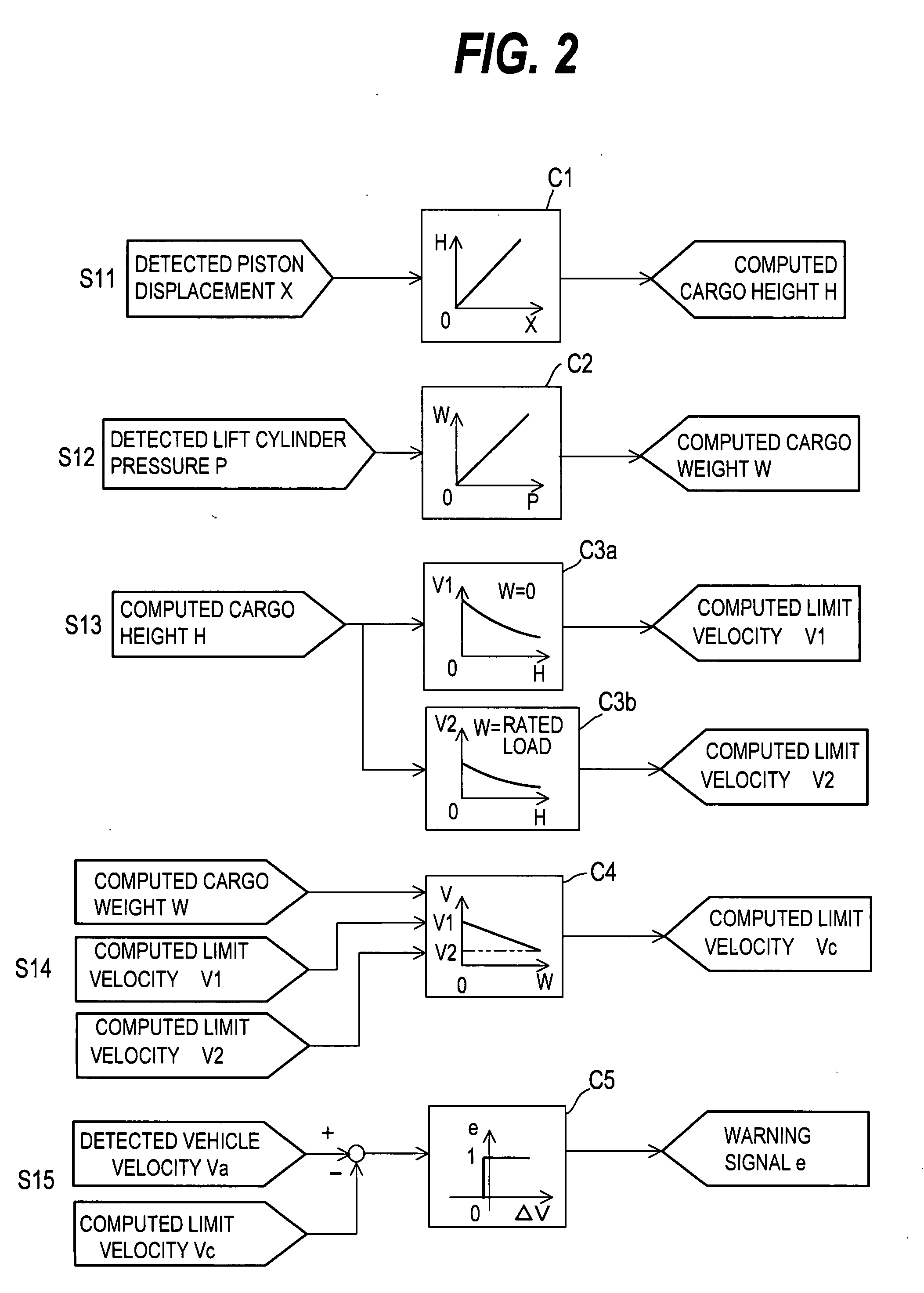
A subject of the present invention is to provide an overturning prevention apparatus for a forklift with various means. A cargo height H is calculated from a piston displacement detected by a displace sensor 21 and a cargo weight W is calculated by pressure P detected by a pressure sensor 22. A controller 20 detects a limit speed V1 in the case of non-cargo weight and a limit speed V2 in the case of the maximum cargo weight. By linearly interpolating the limit speeds V1 and V2, limit velocity Vc in the case that the cargo weight is W by utilizing a minimum turning radius memorized in the controller as a turning radius. If an actual velocity Va measured by a velocity sensor 23 is reached to the limit velocity Vc, the warning device 30 is actuated for warning an operator.

Description

FIELD OF THE INVENTION[0001]The present invention relates to an overturning prevention device for a forklift vehicle.BACKGROUND OF THE INVENTION[0002]In the case that a running forklift vehicle turns without reducing velocity sufficiently, the forklift vehicle might be overturned by applying large lateral force.[0003]In order to prevent for occurring such a phenomenon, the patent document 1 shows a device. The device detects a current steering amount, a cargo position and a cargo weight. In accordance with such detected values, a limit overturning prevention angle is calculated. Further, an overturning prevention velocity is calculated in accordance with the limit overturning prevention angle so that vehicle velocity can be controlled.[0004]Patent Publication 1: Japanese Patent Laid-open Publication 10-175800DISCLOSURE OF THE INVENTIONSubject Solved by the Invention[0005]The above Patent Publication 1 discloses that the limit overturning prevention angle is calculated by detecting a...

Claims


Application Information

Patent Timeline
IPC IPC(8): G06F7/00
CPCB66F17/003
Inventor AKAKI, TOMIHIRO
Owner MITSUBISHI HEAVY IND LTD
Learn More