
Housing for fluid lubrication bearing apparatuses

a technology for fluid lubrication bearings and housings, which is applied in the direction of mechanical equipment, sliding contact bearings, rigid support of bearing units, etc., can solve the problems of reducing affecting the moldability of the housing, and lowering the viscosity of the whole resin, so as to ensure the cleanliness of the inner bearing or the surroundings of the bearing apparatus, avoid modification, deterioration and lowering of the viscosity of the lub

Inactive Publication Date: 2010-03-11
NTN CORP
View PDF27 Cites 4 Cited by
  • Summary
  • Abstract
  • Description
  • Claims
  • Application Information

AI Technical Summary

Benefits of technology

[0010]However, forming the above housing of resins obtained by the methods stated above may cause the following problems. For example, in the former method (adding monoepoxy resin), to increase the affinity of the resin and adhesive, there arises a necessity to add a substantial amount of epoxy resin. This may lower the fluidity (melt viscosity) of the whole resin and may adversely affect the moldability of the housing. Moreover, in the latter method (adding epoxy modified PPS), a low-molecular-weight epoxy component remaining in the epoxy modified PPS decomposes at the molding temperature of the housing, producing a gas. This gas remaining inside the molding leaves voids within the housing, remains on the outer surface of the housing, or causes other problems, which may lower the molding precision of the housing. Moreover, to obtain an epoxy modified resin of this type, complicated and numerous steps need to be carried out, which results in an increase in required production costs. From the foregoing, none of the above-mentioned methods can be said to be an appropriate means for improving the adhesive force of a housing for fluid lubrication bearing apparatuses.
[0011]An object of the present invention is to provide a housing for fluid lubrication bearing apparatuses which has an improved adhesiveness with other components at low costs.

Problems solved by technology

However, forming the above housing of resins obtained by the methods stated above may cause the following problems.
This may lower the fluidity (melt viscosity) of the whole resin and may adversely affect the moldability of the housing.
This gas remaining inside the molding leaves voids within the housing, remains on the outer surface of the housing, or causes other problems, which may lower the molding precision of the housing.
Moreover, to obtain an epoxy modified resin of this type, complicated and numerous steps need to be carried out, which results in an increase in required production costs.
From the foregoing, none of the above-mentioned methods can be said to be an appropriate means for improving the adhesive force of a housing for fluid lubrication bearing apparatuses.

Method used


Image

  • Housing for fluid lubrication bearing apparatuses
  • Housing for fluid lubrication bearing apparatuses
  • Housing for fluid lubrication bearing apparatuses

Examples


example 1

[0103]To clarify the advantages of the present invention, a plurality of resin compositions having different chemical compositions were evaluated for the required characteristics of a housing for fluid lubrication bearing apparatuses. A certain polyphenylene sulfide (PPS) was used as a base resin. Moreover, a carbon fiber and six inorganic compounds having different main constituent elements or different shapes were used as fillers. The combination of these base resins and fillers (carbon fibers and inorganic compounds) and their compounding ratios are as shown in FIGS. 7 and 8.

[0104]It should be noted that in this Example, the following substances were used: LC-5G manufactured by Dainippon Ink And Chemicals, Incorporated as the linear polyphenylene sulfide (PPS) (The amount of Na contained: about 300 ppm), titanium oxide manufactured by Ishihara Sangyo Kaisha, Ltd. (grade: CR-60-2, main constituents: titanium oxide, average diameter: 0.2 μm), zinc oxide manufactured by The Honjyo C...

example 2

[0131]Moreover, to clarify the advantages of the present invention, a plurality of resin compositions with different chemical compositions were evaluated for the characteristics required for the housing 7. A linear polyphenylene sulfide (PPS) was used as the base resin. Moreover, four or five epoxy compounds having different epoxy values were each used as an epoxy compound added to the base resin. Moreover, a carbon fiber was used as the filler. The combinations and compounding ratios of these base resins and epoxy compounds are as shown in FIGS. 11 to 13.

[0132]It should be noted that in this Example, the followings were used: LC-5G manufactured by Dainippon Ink And Chemicals, Incorporated as the linear polyphenylene sulfide (PPS); and Bond-Fast manufactured by Sumitomo Chemical Co., Ltd. (grade: 2C, epoxy value: 0.42 meq / g), Rezeda manufactured by Toagosei Co., Ltd. (grade: GP301, epoxy value: 0.57 meq / g), Bond-Fast manufactured by Sumitomo Chemical Co., Ltd. (grade: E, epoxy value...


PUM

PropertyMeasurementUnit
tensile strengthaaaaaaaaaa
aspect ratioaaaaaaaaaa
vol %aaaaaaaaaa

Abstract

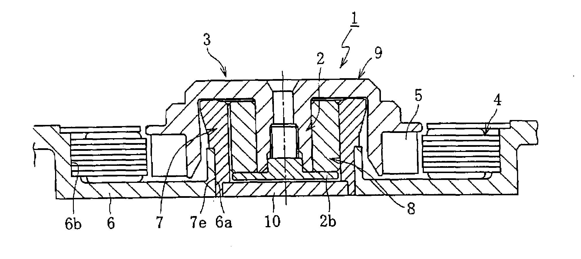
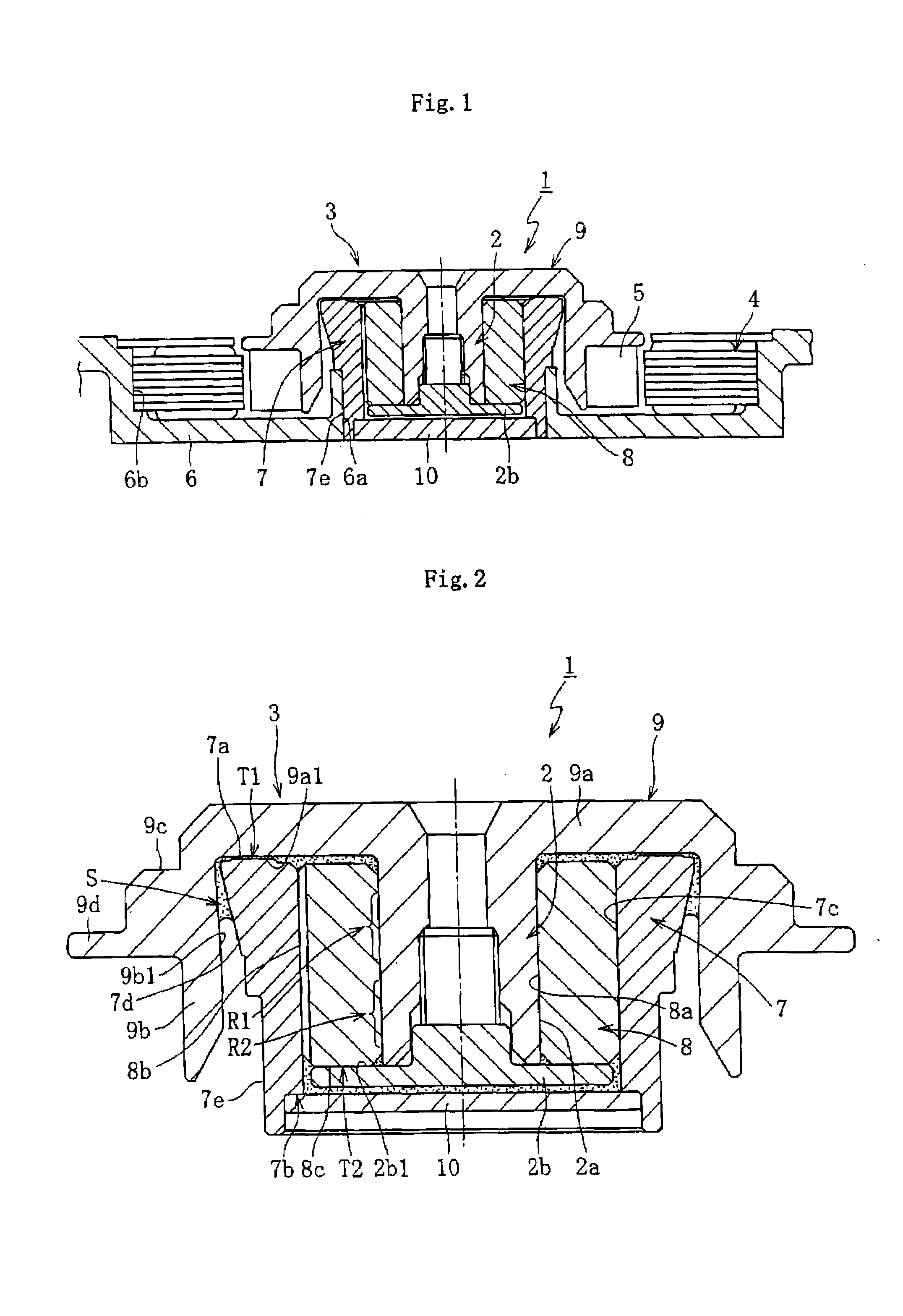
A housing for fluid lubrication bearing apparatuses having improved adhesiveness with other components is provided at low costs.A housing 7 constituting a fluid lubrication bearing apparatus 1 was formed of a resin composition comprising polyphenylene sulfide (PPS) as a base resin, and the ratio of the base resin added to the resin composition was set to not lower than 40 vol % but not higher than 70 vol %. Moreover, a composition prepared by adding an epoxy compound having two or more epoxy groups per molecule of the compound and epoxy value of 0.5 meq / g or more to the resin composition so that the amount of epoxy groups in the resin composition is 8 meq / 100 g or more was used. A carbon fiber was added to the resin composition comprising the base resin in an amount of not less than 10 vol % but not more than 35 vol %. An inorganic compound was further added to the resin composition comprising the base resin and carbon fiber so that the inorganic compound makes up the remainder of the base resin and carbon fiber in the resin composition.

Description

BACKGROUND OF THE INVENTION[0001](1) Field of the Invention[0002]The present invention relates to a housing for fluid lubrication bearing apparatuses. Bearing apparatuses having this housing are suitable for information appliances, for example, in spindle motors for magnetic disk drive units such as HDD, optical disk drive units such as CD-ROM, CD-R / RW, DVD-ROM / RAM, magneto-optic disk drive units such as MD and MO, polygon scanner motors of laser beam printers (LBP), collar wheels of projectors, or electrical machinery and apparatuses, for example, small motors such as fan motors.[0003](2) Description of the Related Art[0004]Enhanced speed, cost reduction, noise reduction, etc., as well as high rotational accuracy, are required for the above various kinds of motors. One of the components which determine these required performance is a bearing which supports spindles of said motors. In recent years, the use of a fluid lubrication bearing having excellent characteristics for the above...

Claims


Application Information

Patent Timeline
Patent Type & Authority Applications(United States)
IPC IPC(8): F16C32/06
CPCF16C17/107H02K7/085F16C35/02F16C2208/52
Inventor MURAKAMI, KAZUTOYOEGAMI, MASAKI
Owner NTN CORP
Learn More