Power source apparatus
a power source and power supply technology, applied in the field of power supply devices, can solve the problems of difficult handling of cooling mediums and lower thermal conductivity of cooling mediums, and achieve the effects of preventing temperature variations of cooling liquids, reducing heat loss, and simplifying structur
- Summary
- Abstract
- Description
- Claims
- Application Information
AI Technical Summary
Benefits of technology
Problems solved by technology
Method used
Image
Examples
embodiment 1
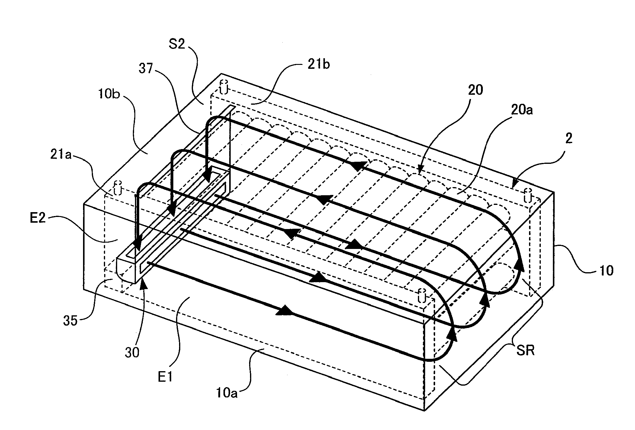
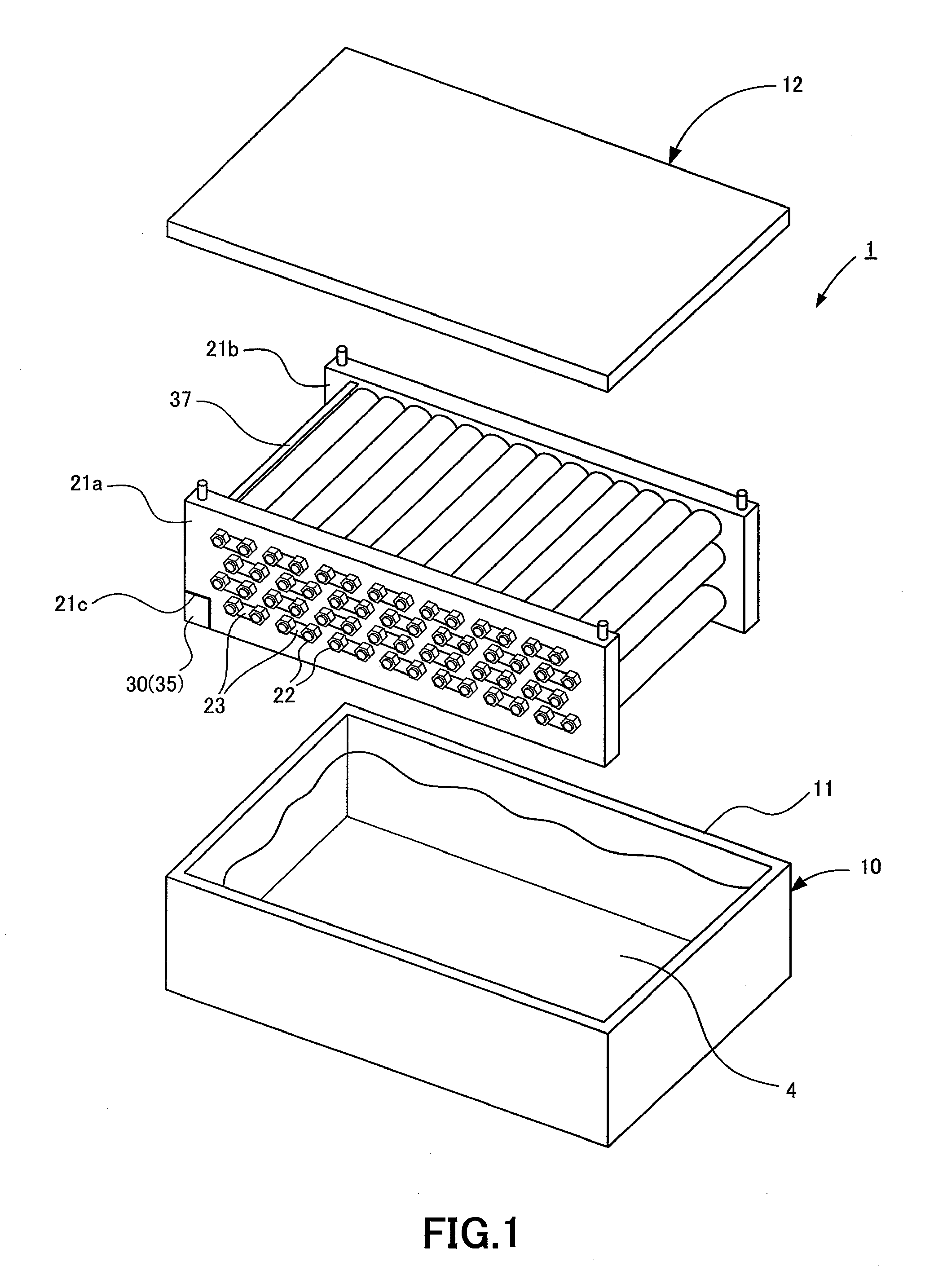
[0039]A power source apparatus in Embodiment 1 of the present invention will be described with reference to FIGS. 1 to 4. FIG. 1 is an exploded perspective view showing a power source apparatus 1 of Embodiment 1. FIG. 2 is a top view showing the power source apparatus 1 of Embodiment 1. FIG. 3 is a schematic diagram showing the outer appearance of a cross flow fan which forms a laminar flow in the power source apparatus 1 of Embodiment 1. FIG. 4 is a side view showing the cross flow fan of the power source apparatus 1.
[0040]The power source apparatus 1 of Embodiment 1 is formed of a battery unit 2 which serves as a power source module, later described, and a case member which includes a lower case 10 having an opening portion 11 and putting the battery unit 2 in and an upper case 12 covering the opening portion 11 of the lower case 10. The lower case 10 and the upper case 12 provide sealed space for housing the battery unit 2. The sealed space is filled with a cooling liquid 4 for u...
embodiment 2
[0076]A power source apparatus in Embodiment 2 of the present invention will be described with reference to FIGS. 9 and 10. FIG. 9 is an exploded perspective view showing a power source apparatus 1a of Embodiment 2. FIG. 10 is a section view showing the power source apparatus 1a in Embodiment 2 of the present invention to explain the flow of a cooling liquid.
[0077]In Embodiment 2, a flow directing portion 40 is provided at a bottom portion of a lower case 10 forming part of a case member as described in Embodiment 1 to direct at least part of a laminar flow of a cooling liquid 4, that is, a branch laminar flow Sr as described in Embodiment 1 between cells 20a. Other structures are identical to those in Embodiment 1, so that they are designated with the same reference numerals as in Embodiment 1 and description thereof is omitted.
[0078]As shown in FIG. 9, the flow directing portion 40 has a plurality of protruding portions 41a which protrude in a direction substantially perpendicular...
PUM
| Property | Measurement | Unit |
|---|---|---|
| length | aaaaa | aaaaa |
| distance | aaaaa | aaaaa |
| height | aaaaa | aaaaa |
Abstract
Description
Claims
Application Information
 - R&D
- Intellectual Property
- Life Sciences
- Materials
- Tech Scout
- Unparalleled Data Quality
- Higher Quality Content
- 60% Fewer Hallucinations
Browse by: Latest US Patents, China's latest patents, Technical Efficacy Thesaurus, Application Domain, Technology Topic, Popular Technical Reports.
© 2025 PatSnap. All rights reserved.Legal|Privacy policy|Modern Slavery Act Transparency Statement|Sitemap|About US| Contact US: help@patsnap.com


