
Method to optimize combustion of liquid fuels

a technology of liquid fuels and combustion methods, applied in combustion-air/fuel-air treatment, machines/engines, mechanical equipment, etc., can solve the problem of not vaporizing liquid particles, and achieve the effect of optimizing combustion

Inactive Publication Date: 2010-03-11
INTERNOVY ENVIRONMENTAL INNOVATIONS +1
View PDF4 Cites 0 Cited by
  • Summary
  • Abstract
  • Description
  • Claims
  • Application Information

AI Technical Summary

Benefits of technology

[0007]In addition, to the gasification, the combustion of fuel is increased by exposing said gasified fuel to ultraviolet light inside the camera.

Problems solved by technology

However, although an adequate vacuum can exist to reach the boiling point of a liquid particle, the liquid particle is not vaporized if there is no adequate volume and an adequate flow so the liquid particle can physically expand as a gas.

Method used


Image

  • Method to optimize combustion of liquid fuels
  • Method to optimize combustion of liquid fuels
  • Method to optimize combustion of liquid fuels

Examples


Embodiment Construction

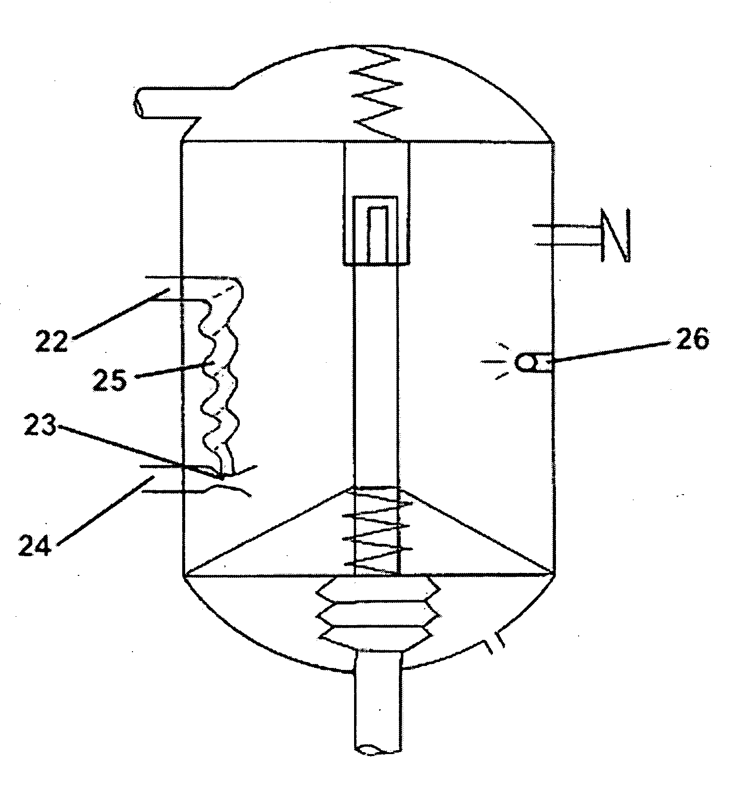
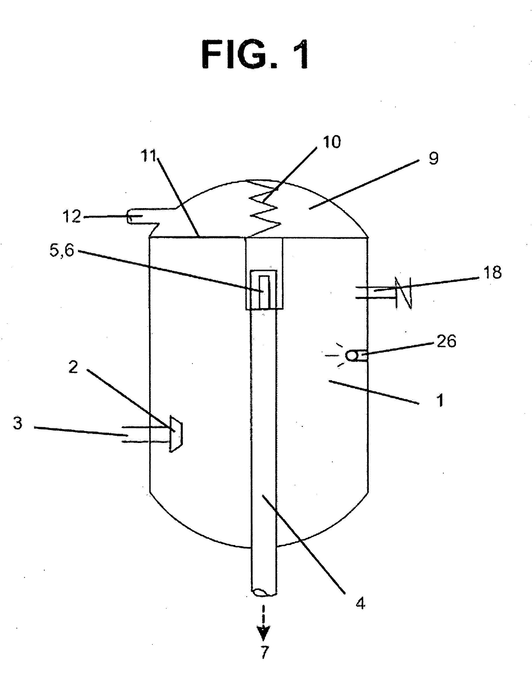
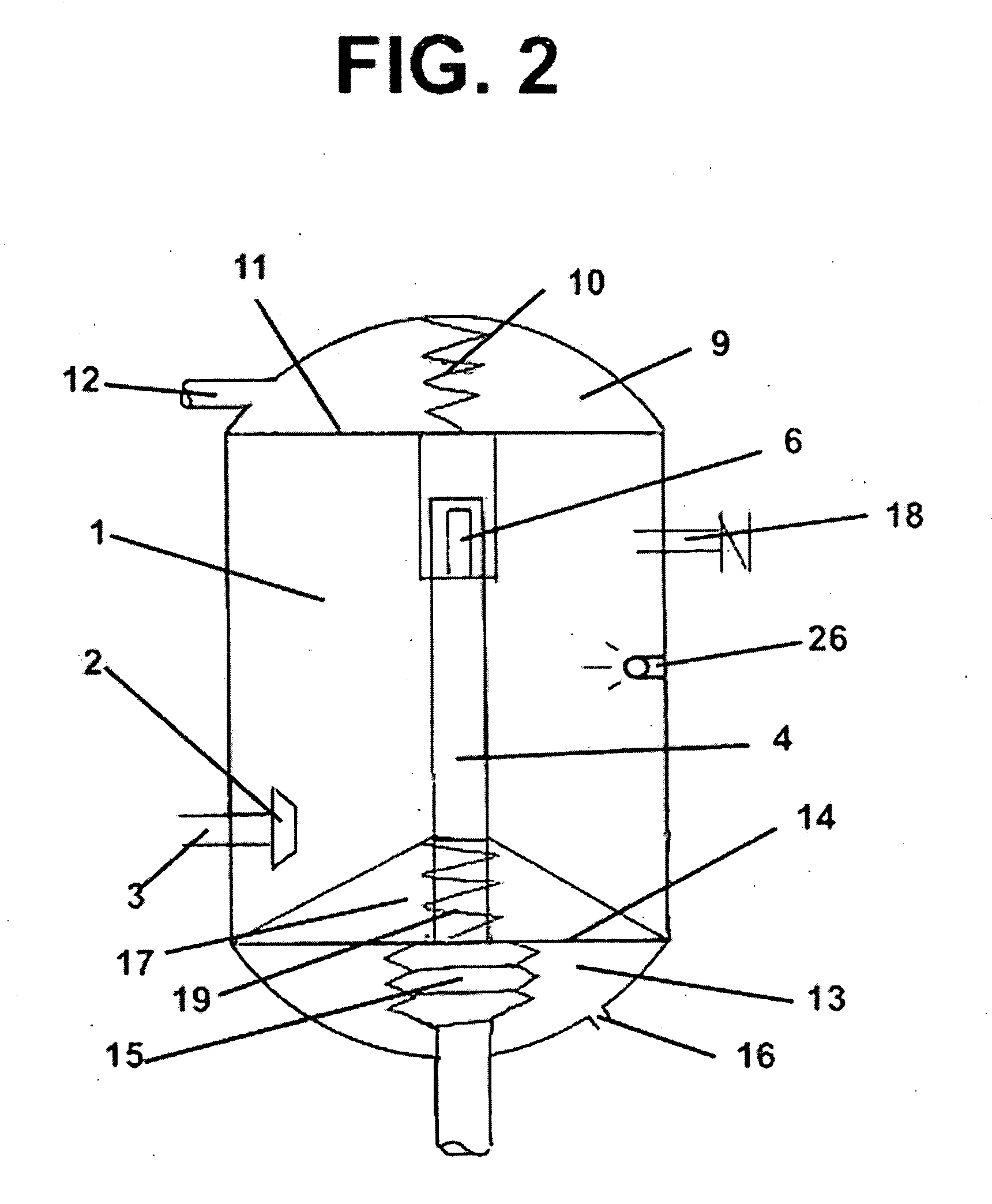
[0061]FIG. 1. Allows seeing technical aspects of the method of the present invention. FIG. 1. shows a closed camera (1) where a vacuum has been created, an atomizer (2) located at the end of the entry line (3) for a liquid fuel, an exit line (4) that allows the gasified fuel flow to leave toward the exterior of the closed camera (1), and a flow control mechanism (5) to regulate the leaving flow toward the exterior of the closed camera (1).

[0062]In a preferred aspect of all versions of the present invention the closed camera has a source of ultraviolet light that illuminates the interior of said closed camera (26) (FIGS. 1-6). Preferably said source is a LED (light emitting diode) (26) that emits ultraviolet light. However, the light source can be any light source that emits light with a wave length less than 500 nanometers (wave length range of ultraviolet light).

[0063]The purpose of the illumination with ultraviolet light is the production of oxygen radicals (production of superoxi...


PUM


Abstract

The invention of the present application provides a method and a device to optimize the combustion of a liquid fuel by means of gasification of said fuel. Gasification of liquid fuel through the method and the device of the present invention is achieved by atomizing liquid fuel that is converted in very fine liquid particles, and wherein the atomization of said very fine liquid particles is done in a closed camera of an adequate volume, and wherein in said closed camera a vacuum has been generated, and wherein in said closed camera there is an adequate flow, and wherein the adequate flow is achieved by means of a flow control mechanism, and wherein the very fine liquid particles, due to the effect of the vacuum, to the proper environment generated by the existence of an adequate volume of the camera, and the adequate flow, are gasified without need of increasing temperature, nor using any mechanical mean inside the camera.

Description

FIELD OF THE INVENTION[0001]The present invention provides a method and a device which purpose is the conversion of liquid fuels to a gaseous state, resulting in more complete combustion with optimal energy efficiency.BACKGROUND OF THE INVENTION[0002]Gasification of liquid fuel to obtain better combustion has been described previously. However, previous descriptions show devices made under the premise that a high superficial tension in small liquid particles makes harder to gasify said particles, and therefore higher temperatures or lower pressures should be used to obtain gasification of said particles. Under the same premise a method has been described in which liquid particles have been broken by complex mechanical means.[0003]By way of example, devices and methods with the mentioned limitations have been described in U.S. Pat. No. 4,083,340 by Furr, U.S. Pat. No. 4,515,134 by Warren, and U.S. Pat. No. 6,257,212 by Hammond.[0004]The invention of the present application presents a...

Claims


Application Information

Patent Timeline
IPC IPC(8): F02M29/00
CPCF02M27/06Y02T10/126F02M31/18F02M27/08Y02T10/12
Inventor LEAL JIMENEZ, JAIRO EDUARDO
Owner INTERNOVY ENVIRONMENTAL INNOVATIONS
Learn More