
Window and combined defence shutter and blind

Inactive Publication Date: 2010-02-25
WILKINS BRIAN MALCOLM
View PDF38 Cites 18 Cited by
  • Summary
  • Abstract
  • Description
  • Claims
  • Application Information

AI Technical Summary

Benefits of technology

[0010]Preferably, the blades are formed from a strong lightweight material such as aluminium or the like. Alternatively, the blades may be formed of a plastics material, which may be further reinforced by the incorporation of a strengthening material such as Kevlar®. These materials may be suitably formed into shape by extrusion, internal spacing within the blade may be left hollow to provide the blade with suitable flexibility.
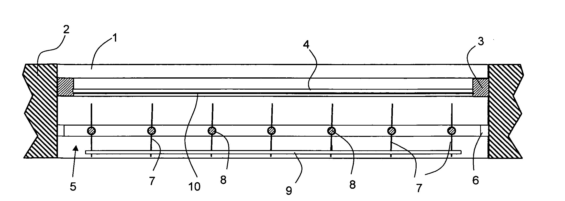
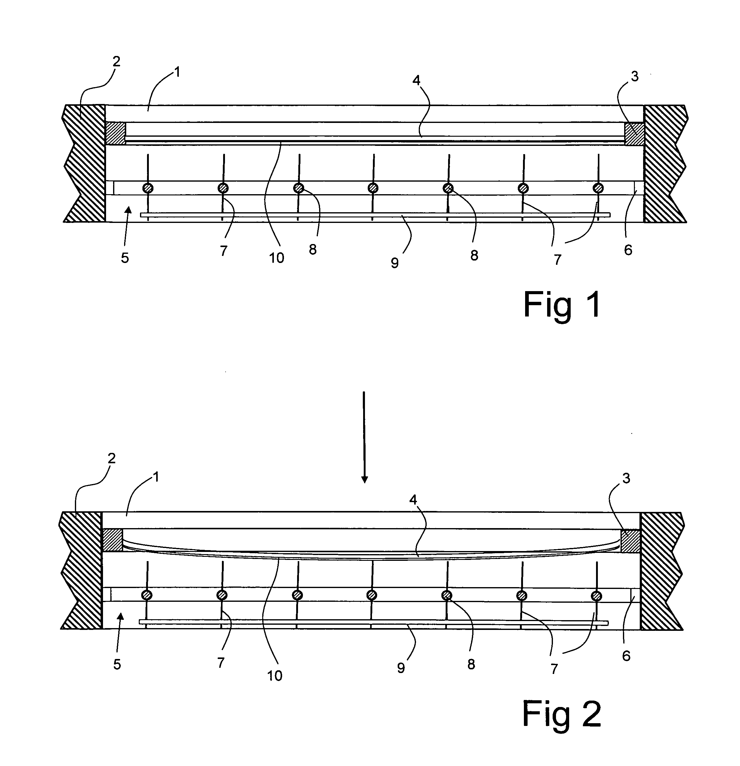
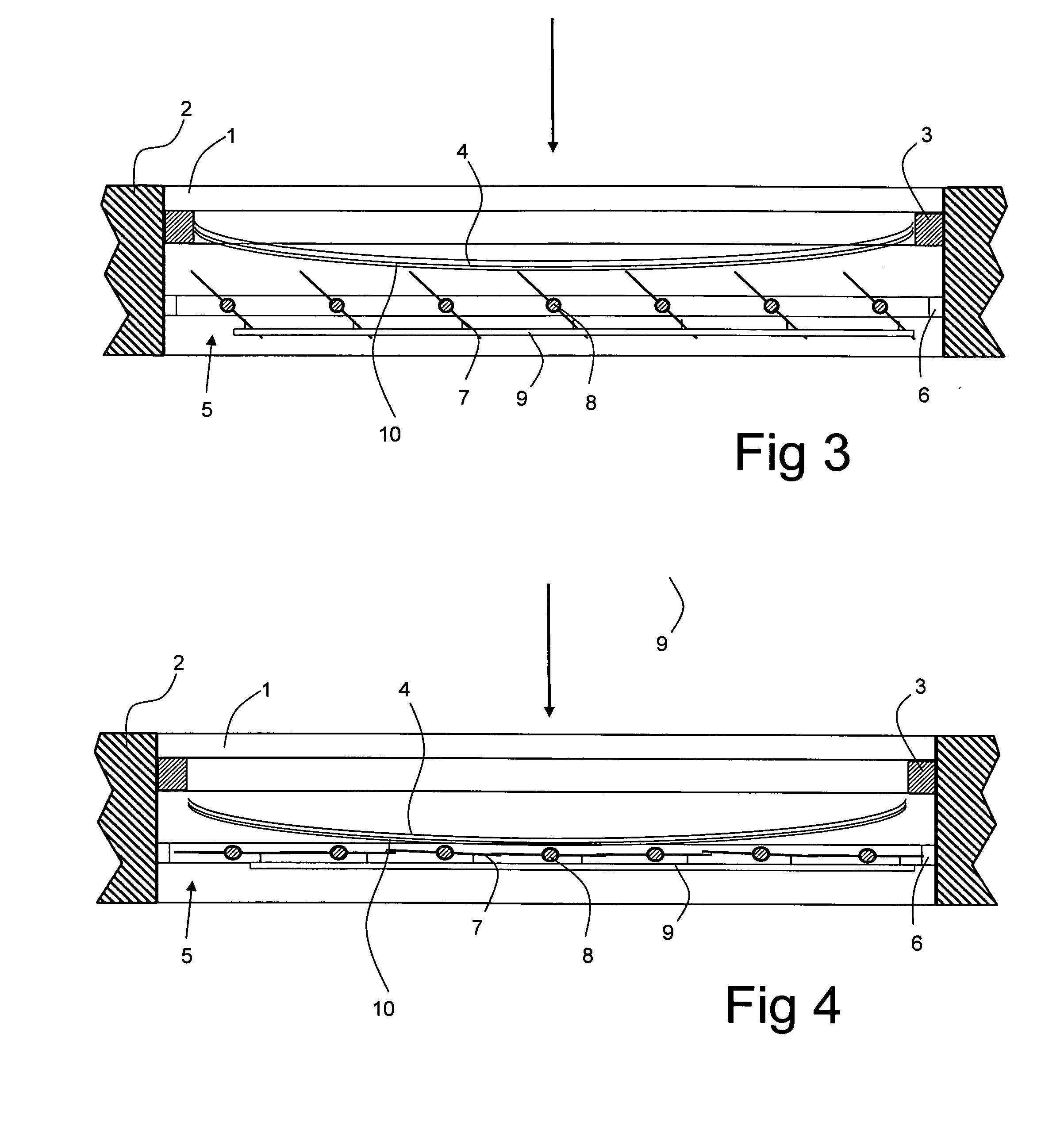
[0011]A blast occurring outside the building triggers the closure of the blind. The force of the blast causing the glass of the window to break, or flying debris hitting the glass causing it to shatter, distorts both the window and in turn the anti-shatter material on the inside of the window. The window and anti-shatter material contact at least a portion of a pointed edge of at least one of the blades when in the open position to rotate it to the closed position, thereby preventing ingress of the pressure wave and glass from the window into the building.
[0020]All the blinds in accordance with different aspects of the invention provide security from attempted break-ins to the building, while giving the appearance of conventional vertical blinds, as well as protecting the occupants from the effects of explosions outside the building.

Problems solved by technology

The need for such protection has arisen over recent years with the increase in both terrorist attacks, and crime.
In many of the terrorist attacks involving bomb blasts a high percentage of the deaths suffered have been caused by the absence of any protection from the flying debris of the blast and glass from broken windows.

Method used


Image

  • Window and combined defence shutter and blind
  • Window and combined defence shutter and blind
  • Window and combined defence shutter and blind

Examples


Embodiment Construction

[0029]Referring first to FIGS. 1 to 4, a window opening 1 in a building 2 has a window frame 3 mounted therein in conventional manner, the window frame mounting a glass sheet 4 (alternatively, a sealed double-glazing unit could be used). A combined defence shutter and window blind 5 (hereinafter referred to as a blind) is also mounted within the window opening 1, inside the building relative to the window 3, 4. The blind 5 consists of a frame 6 which may be mounted in the window opening 1 so as to hinge open, for example for access to the window for cleaning and maintenance or for emergency egress from the building. A plurality of parallel vertical blades 7 are mounted within the frame. Each blade 7 has a steel reinforcing rod 8 passing therethrough, the rods 8 being secured in the frame in such a manner as to permit rotation of the blades around the longitudinal axis of the rods. The blades 7 are shaped so as to disguise the presence of the rods 8 and to give the appearance of conv...


PUM

PropertyMeasurementUnit
Diameteraaaaaaaaaa
Pressureaaaaaaaaaa
Diameteraaaaaaaaaa

Abstract

A combined defence shutter and blind is located in a window opening inwardly of the window. The shutter comprises a shutter frame secured in the window opening, and a plurality of parallel blades extending across the shutter frame, each said blade having in cross-section a shape which includes a point at each opposed edge of the blade and having a reinforcing axial member extending therethrough and engaged in respective opposing sides of the shutter frame. The blades are linked together and rotatable such that rotation of one blade induces the other blades to rotate simultaneously between a closed position, in which the blades lie substantially parallel to the window so as to form a continuous shutter, and an open position substantially normal to the closed position. The window has anti-shatter material extending over the entire inner surface thereof, whereby, in the event of an explosion outside the window causing a pressure wave to blow the window inwardly of the building, the window and anti-shatter material contacting at least a portion of a pointed edge of at least one of the blades when in the open position to rotate to the closed position, thereby preventing ingress of the pressure wave and glass from the window into the building.

Description

FIELD OF THE INVENTION [0001]This invention relates to a window located in a window opening in a building and having a combined defence shutter and blind suitable for resisting the effects of an explosion outside the building. The invention also provides ballistics-resisting defence shutters.BACKGROUND TO THE INVENTION [0002]The use of security shutters in windows is well known in preventing unauthorised access through a window, i.e. preventing burglary. Equally, the use of various types of blinds for use with windows, in which the strips are rotatable so as to overlap to form a continuous closed surface or to extend normally to the window to allow light and air through is also well known.[0003]The combination of these two elements is also already known from my published application WO02 / 06620.[0004]However it has since been found that the combination of the security shutter and blind with a modified window can be used as a defence screen against a blast occurring outside the buildi...

Claims


Application Information

Patent Timeline
IPC IPC(8): E06B7/08E06B9/02E06B5/12F41H5/00
CPCE06B5/12F41H7/035F41H5/26E06B9/02F41H5/0442F41H5/0478
Inventor WILKINS, BRIAN MALCOLM
Owner WILKINS BRIAN MALCOLM
Learn More