Power conversion system and power conversion method thereof

a power conversion system and power conversion technology, applied in the direction of electric lighting sources, lighting apparatuses, electric light sources, etc., can solve the problem of achieve small power consumption of the control unit, reduce system cost, and improve stability

Inactive Publication Date: 2010-02-18
NOVATEK MICROELECTRONICS CORP
View PDF9 Cites 3 Cited by
  • Summary
  • Abstract
  • Description
  • Claims
  • Application Information

AI Technical Summary

Benefits of technology

[0008]First, because the driving unit and the control unit are respectively and independently powered, the control unit has the better stability.
[0009]Second, the driving unit and the control unit are respectively and independently powered and the power consumption of the control unit is small. So, a capacitor with the lower capacitance can be selected to filter the DC power inputted to the control unit so that the system cost can be reduced.
[0010]Third, the power ripple of the DC power inputted to the control unit is greatly reduced. So, the difficulty of the circuit design can be reduced.

Problems solved by technology

Second, the driving unit and the control unit are respectively and independently powered and the power consumption of the control unit is small.

Method used


Image

  • Power conversion system and power conversion method thereof
  • Power conversion system and power conversion method thereof
  • Power conversion system and power conversion method thereof

Examples


Embodiment Construction

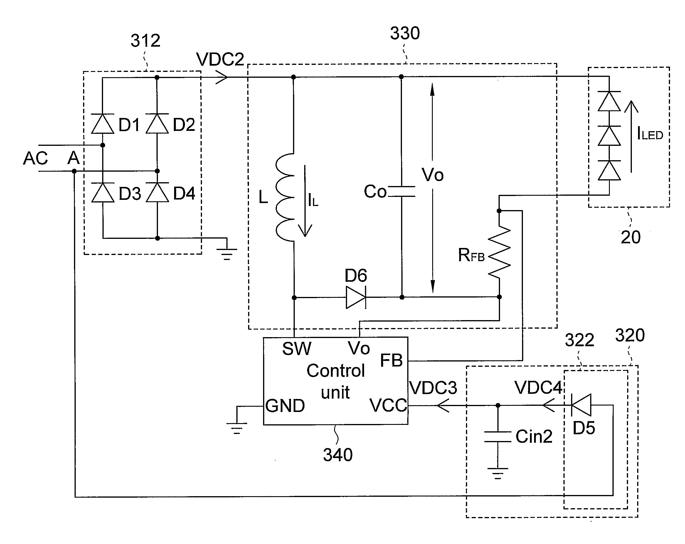
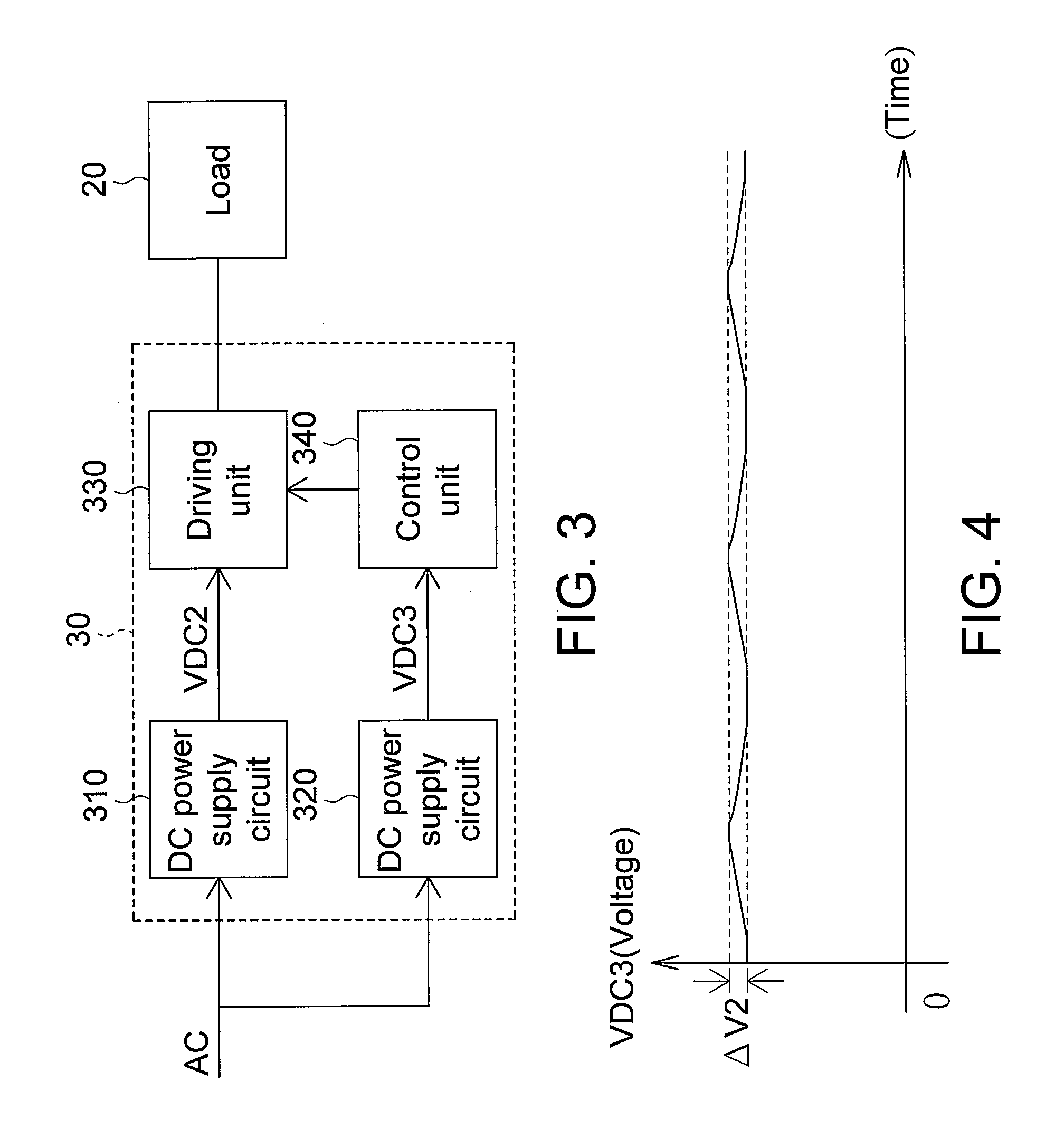
[0021]FIG. 3 is a schematic illustration showing a power conversion system 30 for driving a load according to a preferred embodiment of the invention. FIG. 4 shows a waveform of a DC power. Referring to FIGS. 3 and 4, the power conversion system 30 includes a driving unit 330, a DC power supply circuit 310, a control unit 340 and a DC power supply circuit 320. The control unit 340 controls the driving unit 330 to drive a load 20. The DC power supply circuit 310 converts an AC power AC into a DC power VDC2 outputted to the driving unit 330. The DC power supply circuit 320 converts the AC power AC into a DC power VDC3 outputted to the control unit 340.

[0022]The DC power supply circuit 310 and the DC power supply circuit 320 respectively and independently supply the powers to the driving unit 330 and the control unit 340. So, the stability of the control unit 340 cannot be influenced even if the DC power VDC2 has the very large power ripple and noise. In addition, as shown in FIG. 4, t...


PUM


Abstract

A power conversion system and a power conversion method thereof. The power conversion system includes a driving unit, a control unit, a first direct current (DC) power supply circuit and a second DC power supply circuit. The control unit controls the driving unit to drive a load. The first DC power supply circuit converts an alternating current (AC) power into a first DC power outputted to the driving unit, and the second DC power supply circuit converts the AC power into a second DC power outputted to the control unit.

Description

[0001]This application claims the benefit of Taiwan application Serial No. 97131340, filed Aug. 15, 2008, the subject matter of which is incorporated herein by reference.BACKGROUND OF THE INVENTION[0002]1. Field of the Invention[0003]The invention relates in general to a power conversion system and a power conversion method thereof, and more particularly to a power conversion system for respectively and independently supplying electric powers to a driving unit and a control unit, and a power conversion method thereof.[0004]2. Description of the Related Art[0005]FIG. 1 (Prior Art) is a schematic illustration showing a conventional power conversion system 10 for driving a load. FIG. 2 (Prior Art) shows a waveform of a direct current (DC) power. Referring to FIGS. 1 and 2, the conventional power conversion system 10 includes a rectifying unit 110, a capacitor Cin1, a control unit 140 and a driving unit 130. The rectifying unit 110 and the capacitor Cin1 respectively rectify and filter ...

Claims


Application Information

Patent Timeline
Patent Type & Authority Applications(United States)
IPC IPC(8): H02M7/06
CPCH05B33/0809H02M7/06H05B45/3725H05B45/375H05B45/38
Inventor LIU, YI-TEHSIEH, CHIH-YUANYEN, CHIH-JENCHENG, LAN-SHAN
Owner NOVATEK MICROELECTRONICS CORP
Why Eureka
Try Eureka