
Si-o containing hydrogenated carbon film, optical device including the same, and method for manufacturing the si-o containing hydrogenated carbon film and the optical device

a hydrogenated carbon film and si-o technology, applied in the field of transparent thin films, can solve the problems of difficult to greatly change the refractive index of conventional optical materials, and the design of refractive index modulated-type diffractive optical elements is greatly limited, so as to achieve favorable adaptability, high diffraction efficiency, and high transparency

Inactive Publication Date: 2010-02-18
SUMITOMO ELECTRIC IND LTD
View PDF14 Cites 54 Cited by
  • Summary
  • Abstract
  • Description
  • Claims
  • Application Information

AI Technical Summary

Benefits of technology

[0055]According to the present invention as described above, it is possible to provide a refractive index modulated-type diffractive optical element having a large amount Δn of refractive index change (i.e., high diffraction efficiency), high transparency for the ultraviolet light range as well as the visible light range, and favorable adaptability to generally-used optical elements, and provide an Si—O containing hydrogenated carbon film serving as an optical film suitable for being used for the diffractive optical element.
[0056]Further, it is also possible to provide various optical elements fabricated by using such an Si—O containing hydrogenated carbon film, and provide various optical devices including those optical elements.

Problems solved by technology

However, it is difficult to greatly change the refractive index of conventional optical materials, and for example, a Ge-doped silica glass has a possible refractive index change Δn as small as approximately 0.001, and photopolymers also have a possible refractive index change Δn as small as approximately 0.08.
In comparison with the relief-type diffractive optical element, therefore, the refractive index modulated-type diffractive optical element is greatly limited in designing thereof in the case of using an optical material having a small Δn.

Method used


Image

  • Si-o containing hydrogenated carbon film, optical device including the same, and method for manufacturing the si-o containing hydrogenated carbon film and the optical device
  • Si-o containing hydrogenated carbon film, optical device including the same, and method for manufacturing the si-o containing hydrogenated carbon film and the optical device
  • Si-o containing hydrogenated carbon film, optical device including the same, and method for manufacturing the si-o containing hydrogenated carbon film and the optical device

Examples


examples 1-3

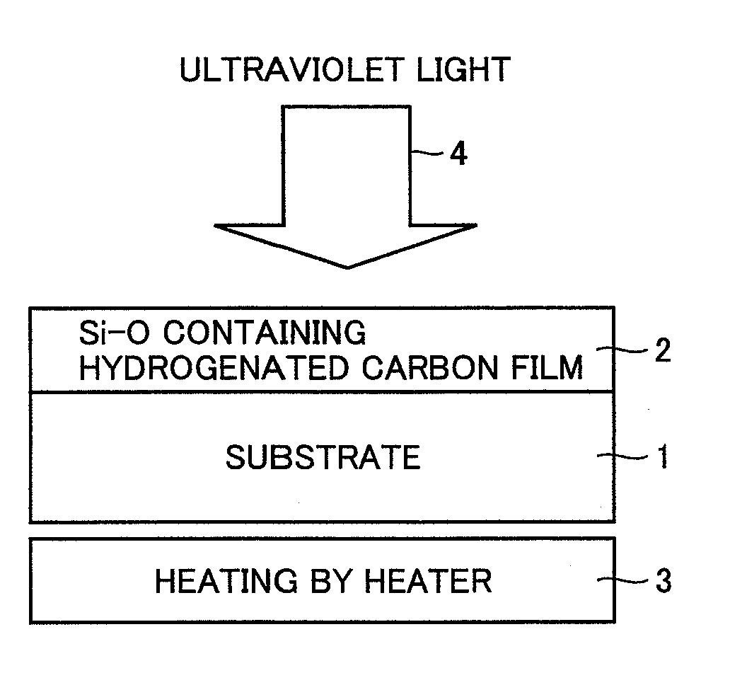
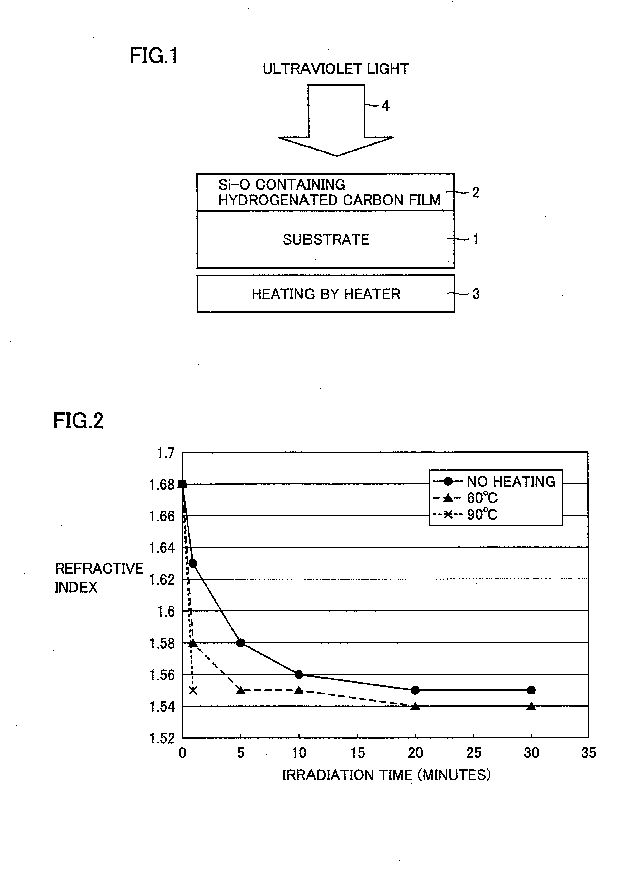
[0164]Examples 1 and 2 show typical and preferable Si—O containing hydrogenated carbon films according to the present invention. In each of the Si—O containing hydrogenated carbon films in Examples 1, 2, it is found that the refractive index just after the film formation for light of 520 nm wavelength falls within the range for the condition of the present invention, i.e., from at least 1.56 to at most 1.76, that the extinction coefficient for light of 248 nm wavelength is in the more preferable range, i.e., less than 0.12 (see Table 2), and that the refractive index and the extinction coefficient are decreased by the energy beam (KrF excimer laser) irradiation (see Table 4). Further, in each of the films of Examples 1 and 2, the amount of refractive index change is in the more preferable range of at least 0.10 and at most 0.30 for the visible light range, and the extinction coefficient is not more than 0.005 resulting in sufficient transparency (see Table 4). Further, in each of Ex...

examples 4-7

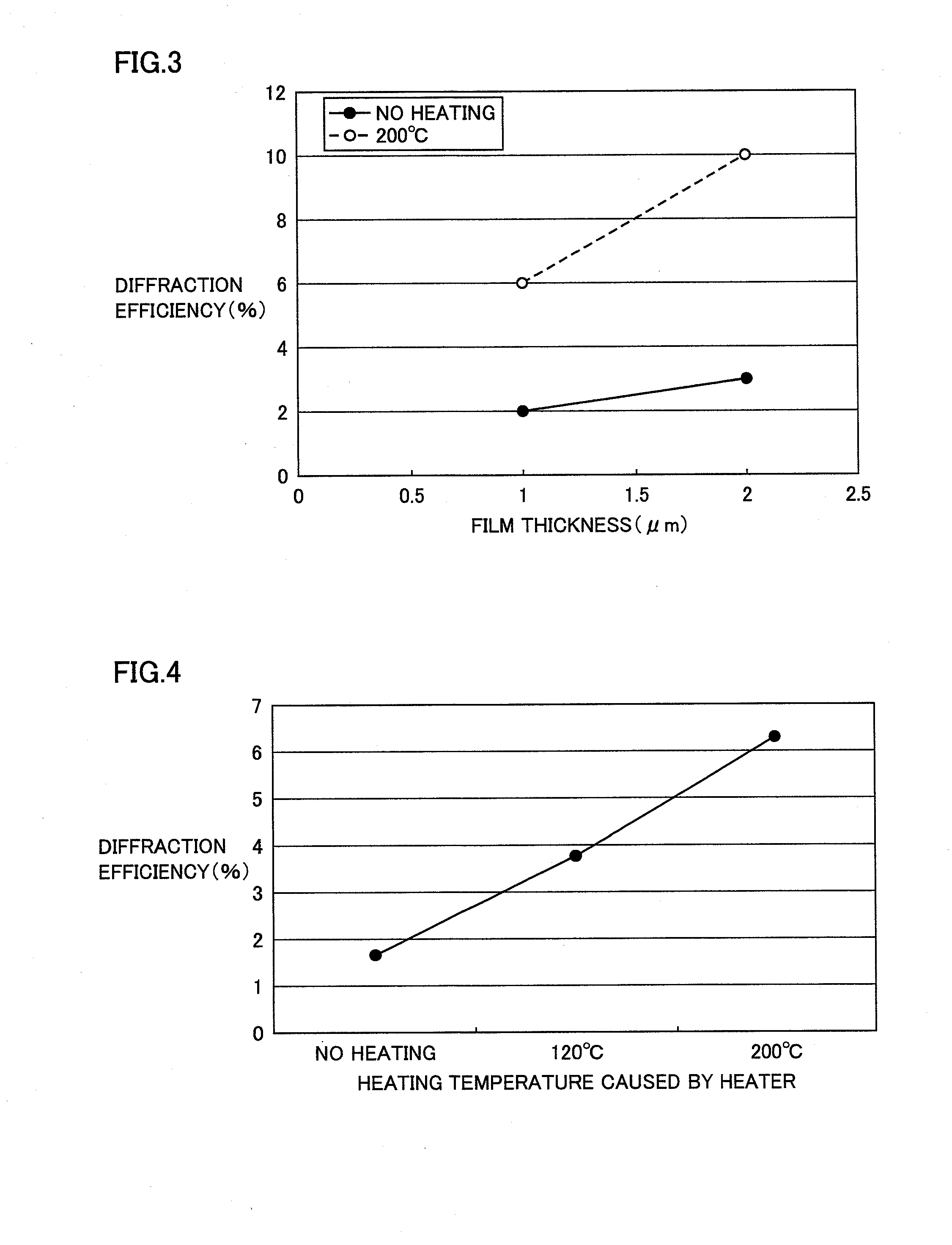
[0172]Examples 4, 5 were similar to Example 3, except that the conditions for energy beam irradiation (types of applied laser) were changed (see Table 3). It is found that in each of Examples 4, 5 as well, the diffraction efficiency is high and the film unevenness is small as in Example 3 (see Table 3).

[0173]In Example 6, on the Si—O containing hydrogenated carbon film obtained under the same conditions for deposition as those in Example 1 (see Table 1), a gold mask was patterned by a lift-off method, and the refractive index of the film was modulated by exposure using synchrotron radiation (energy of 50 to 3000 eV) (see Table 3). The gold mask was then removed by etching, so that there was formed a refractive index modulated-type diffraction lens having a function of converging visible light.

[0174]In Example 7, a refractive index modulated-type diffractive optical element was fabricated with use of the film obtained under the same conditions for film formation as those for the Si—O...

example 10

[0179]The Si—O containing hydrogenated carbon film deposited under the conditions for film formation in Example 10 (see Table 1) has values close to the upper limit of the more preferable range in the present invention, as to the refractive index for the visible light range (wavelength of 520 nm) and the extinction coefficient for the ultraviolet light range (wavelength of 248 nm). More specifically, in the Si—O containing hydrogenated carbon film before the energy beam irradiation, the refractive index was 1.76, the extinction coefficient for the ultraviolet light range was 0.1, and the amount of refractive index change was 0.30 (see Table 2, Table 4).


PUM

PropertyMeasurementUnit
Temperatureaaaaaaaaaa
Thicknessaaaaaaaaaa

Abstract

An Si—O containing hydrogenated carbon film as an optical film has a refractive index in a range from at least 1.48 to at most 1.85 for light of 520 nm wavelength and an extinction coefficient of less than 0.15 for light of 248 nm wavelength, wherein the refractive index and the extinction coefficient are decreased with energy beam irradiation. By utilizing such an Si—O containing hydrogenated carbon film, it is possible to provide various types of optical elements and an optical device including the same.

Description

TECHNICAL FIELD[0001]The present invention relates to an optical device for use in various optical fields such as information communication, information recording, image pickup, and image display, and a material therefor, and more particularly relates to a transparent thin film having a refractive index changeable by energy beam irradiation.BACKGROUND ART[0002]Various optical thin films are used so as to control light in the optical fields such as information communication, information recording, image pickup, and image display. Oxide thin films such as SiO2 and TiO2 and fluoride thin films such as MgF2 are used as typical optical thin film materials, and these are utilized for antireflection films, mirrors, filters, and others. Moreover, diffractive optical elements to which optical thin films are applied are used for various applications.[0003]The diffractive optical elements are mainly classified into a relief type and a refractive index modulated type. The relief-type diffractiv...

Claims


Application Information

Patent Timeline
IPC IPC(8): G02B27/42G02F1/29G02B27/28G02B5/32H05H1/24G02B1/12
CPCB82Y30/00Y10S427/106C01B31/0206G02B1/105G02B3/0012G02B3/0087G02B5/1857G02B27/283G03H1/02G03H2001/0268H04N9/3129H04N9/3161H04N9/3167H04N9/3197B82Y40/00C01B32/15G02B1/14
Inventor AKAHANE, YOSHIHIROIMAI, TAKAHIROMATSUURA, TAKASHIKATAYAMA, TETSUYAUSHIRO, TOSHIHIKO
Owner SUMITOMO ELECTRIC IND LTD
Learn More