
Method for simultaneous detection of a plurality of RFID tags using multiuser detection

a multi-user detection and simultaneous detection technology, applied in the field of electronic identification systems, can solve the problems of more complicated time-dependent behavior that differentiates rfid tags, and achieve the effect of accurately distinguishing each of the individual responses and reducing the latency of rfid detection

Active Publication Date: 2010-02-18
COLLISION COMM
View PDF18 Cites 30 Cited by
  • Summary
  • Abstract
  • Description
  • Claims
  • Application Information

AI Technical Summary

Benefits of technology

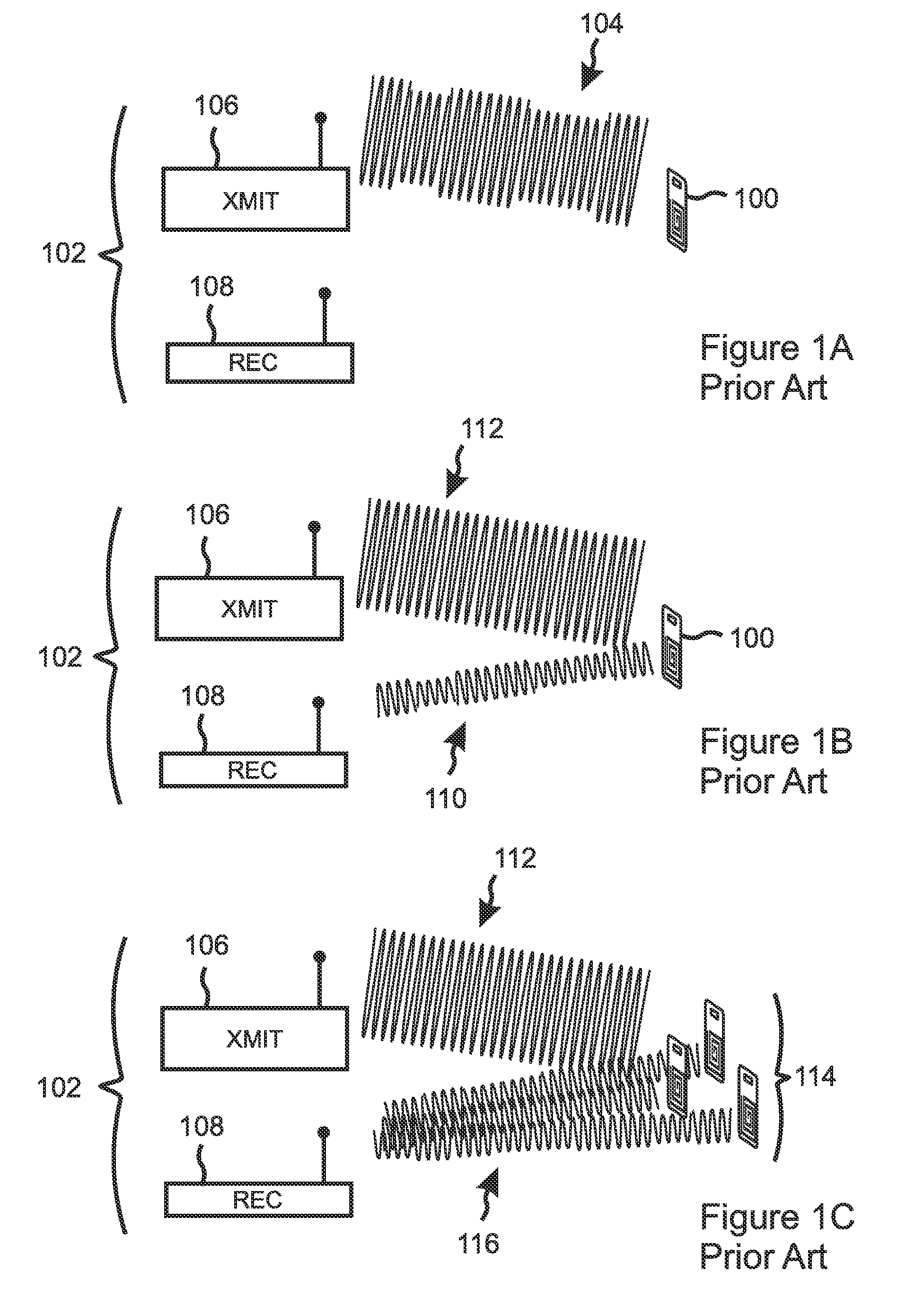
[0012]A method is claimed that applies multiuser detection (MUD) analysis to an aggregated RF response received from a plurality of simultaneously queried RFID tags, so as to accurately distinguish each of the individual responses included in the aggregated RF response. If the aggregated RF response includes responses from only a subset of the simultaneously queried RFID tags, for example due to use of a MAC protocol, the steps of receiving an aggregated RF response and applying MUD analysis are repeated until the responses of all of the queried RFID tags have been distinguished. By enabling an RFID detector to simultaneously distinguish the responses of several RFID tags, the claimed method significantly reduces RFID detection latency in cases when multiple RFID tags are simultaneously queried.
[0014]Some embodiments of the present invention enhance the MUD analysis by expanding on the number of “dimensions” that can be used to differentiate the signals from the RFID tags. Some of these embodiments incorporate a multi-frequency dimension by simultaneously transmitting carrier waves at more than one frequency, for example at a plurality of equally-spaced frequencies. Other embodiments incorporate additional spatial dimensions by deploying multiple RF detection antennae at separated locations.
[0032]Another general aspect of the present invention is an apparatus for distinguishing responses received from a plurality of simultaneously queried RFID tags. The apparatus includes an RF transmitter that is able to transmit a querying RF signal to the plurality of RFID tags, an RF receiver that is able to receive an aggregated RF response from the plurality of RFID tags, an RF characterizer that is able to characterize the aggregated RF response according to a plurality of characteristics, the plurality of characteristics including at least RF amplitude and RF phase, and a computer controlled by software that is able to direct the computer to estimate at least one parameter pertaining to the characterized aggregated RF response, the at least one parameter including a number of RFID tag responses included in the aggregated RF response, the software being further able to direct the computer to apply multiuser detection to the aggregated RF response according to the at least one estimated parameter, so as to distinguish each of the RFID tag responses included in the aggregated RF response.

Problems solved by technology

There may even be more complicated time-dependent behavior that differentiates the RFID tags, for example if some of the signals are reflected from various objects.

Method used


Image

  • Method for simultaneous detection of a plurality of RFID tags using multiuser detection
  • Method for simultaneous detection of a plurality of RFID tags using multiuser detection
  • Method for simultaneous detection of a plurality of RFID tags using multiuser detection

Examples


Embodiment Construction

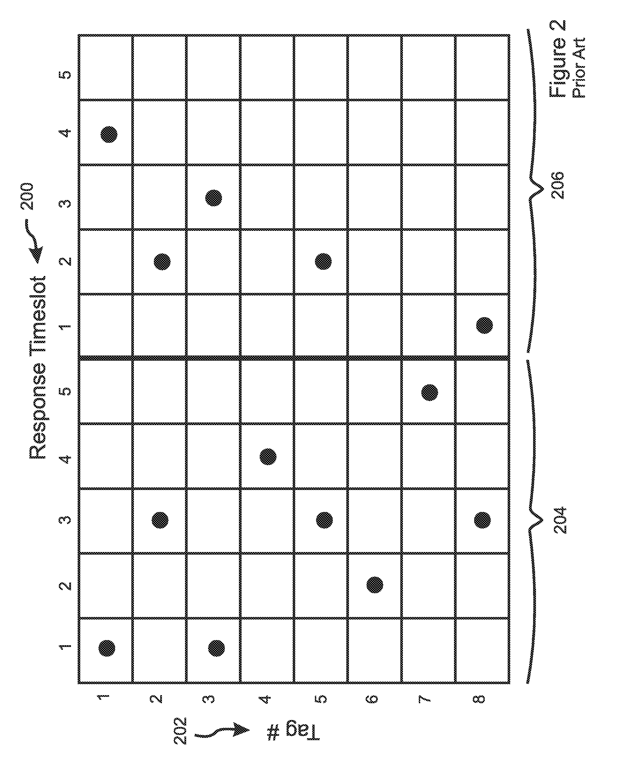
[0051]Based on current RFID designs, a problem occurs when a plurality of RFID tags is simultaneously queried by an RFID detector, for example a plurality of RFID tags that are attached to each product carried by a shipping pallet. In such a case the detector will receive a nearly simultaneous response from every tag that is located within its detection range, resulting in collisions of the data packets transmitted by the tags. Prior art approaches have implemented protocols that cause packets to transmit their information at random times, and to re-transmit until a collision-free transmission is achieved. The present invention applies Multi-User Detection (“MUD”) to distinguish overlapping packets, thereby reducing or eliminating the need for random delays and / or re-transmissions.

[0052]Signal Model

[0053]So as to understand how the present invention solves this problem, it is helpful first to understand the physics and define a representative signal model that incorporates collision...


PUM


Abstract

A method and apparatus are disclosed that apply multiuser detection (MUD) analysis to an aggregated RF response from a plurality of simultaneously queried RFID tags, so as to distinguish the individual tag responses. The claimed method thereby significantly reduces RFID detection latency when multiple tags are simultaneously queried. Some embodiments transmit carrier waves at more than one frequency, such as a plurality of equally-spaced frequencies, so as to enhance the MUD analysis by incorporating a multi-frequency dimension. Other embodiments incorporate additional spatial dimensions by deploying multiple RF detection antennae at separated locations. The number of colliding tag responses must be estimated before MUD analysis can be applied. In some embodiments other signal parameters must be estimated, such as signal bias and an impulse function for each responding tag that characterizes alterations of the RF signal while in transit due to propagation distance, passage through intervening objects, and reflections.

Description

RELATED APPLICATIONS[0001]This application claims the benefit of U.S. Provisional Applications No. 61 / 188,738, filed Aug. 12, 2008, which is herein incorporated by reference in its entirety for all purposes.FIELD OF THE INVENTION[0002]The invention relates to electronic identification systems, and more particularly to RFID tag reading systems.BACKGROUND OF THE INVENTION[0003]RFID tags are identification tags that can be detected and “read” by radio frequency communication. The use of this technology is growing very rapidly, and is being, or is expected to be, applied in a wide variety of applications, ranging from warehouse inventory control, shipping and receiving, shipment tracking, retail sales (e.g. supermarket check-out), building security (e.g. employee ID tags), and military asset tracking. In many of these applications, RFID tags have already, or will soon, replace barcodes as the primary method of automatic item detection and identification.[0004]Typically, RFID technology ...

Claims


Application Information

Patent Timeline
Patent Type & Authority Applications(United States)
IPC IPC(8): H04Q5/22
CPCH04Q9/00H04Q2209/753H04Q2209/47
Inventor NIEDZWIECKI, JOSHUA D.BASU, PRABAHAN
Owner COLLISION COMM
Learn More