
Method and device for the activation of an electropneumatic valve of a pressure medium-actuated position controller

a technology of electropneumatic valve and position controller, which is applied in the direction of process and machine control, servomotors, instruments, etc., can solve the problems of failure of pressure medium, failure of electropneumatic valve as pilot control valve, failure of safe behavior as a result of pressure medium failure,

Inactive Publication Date: 2010-02-18
ABB TECH AG
View PDF14 Cites 11 Cited by
  • Summary
  • Abstract
  • Description
  • Claims
  • Application Information

AI Technical Summary

Benefits of technology

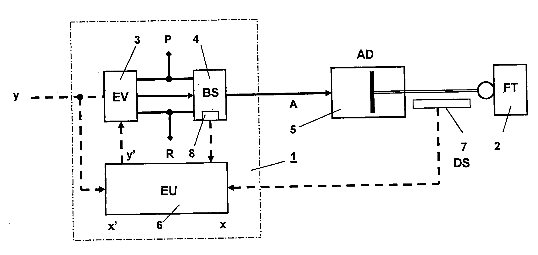
[0022]determining an expected directional reaction (x′) of the regulation or process variable to the stipulated (assigned) manipulated variable (y),
[0027]According to an exemplary embodiment, by means of the electrical emergency signal, the pressure medium acting upon the booster stage can be enclosed via a neutral position of the electropneumatic valve, so as to achieve a leaktight closure. Moreover, an electrical activation signal can be transmitted to the electropneumatic valve, which can cause the pressure medium acting upon the booster stage to be discharged to the atmosphere via the exhaust air duct of the electropneumatic valve. A reversal of activation opposite to the original direction is thereby achieved, so that the position controller can assume its initial position.
[0026]An advantageous aspect of the above-described exemplary method is that, independent of the switching position of the pressure medium-operated position controller, the desired blocking fail-safe behavior can be ensured, in the event of a failure of pneumatic energy, by means of an active activation of the pneumatic pilot control. Moreover, this ensures that the electropneumatic valve of the pilot control cannot continue to be fed with outflowing pressure medium from the actuating drive. This adaptive control forms the basis for sending a diagnostic message corresponding to the fault situation to a central control unit (e.g., CPU). When a potential pneumatic energy failure is detected, the new activation signal required for the desired blocking may only need to be applied for a short time. Thereafter, the actuating signal stipulated by the process regulation and control loop can be transmitted, unchanged, to the electropneumatic valve, with the effect that, in the event of a possible faulty detection of a pneumatic energy failure, regulation can continue to operate, unaffected. It is also conceived that if a pneumatic energy failure is detected, the activation signal required for the desired blocking can be applied, perhaps permanently, and further normal operation solely by interaction between an overriding control and an operator can be achieved. This is practical especially when a corresponding diagnostic message has previously been transmitted to the overriding control, whereupon the operator has to react in order to rectify the fault.
[0028]According to an exemplary embodiment, an evaluation unit is provided, as an electronic circuit, for example, to determine an expected directional reaction of the regulation or process variable to the stipulated manipulated variable, and compare the expected directional reaction with the actual directional reaction. In signal processing terms, the expected directional reaction can, for example, be formed by means of the mathematical relation of the first derivative of the expected speed signal dx′ / dt, and the comparison with the measured speed signal dx / dt is carried out. If the measured speed signal dx / dt and the expected speed signal dx′ / dt possess the same direction due to the same signs, a pressure medium failure can be established as a fault situation when the expected direction does not correspond to the measured direction of the actuating drive, i.e., the signs are different.
[0029]According to an exemplary embodiment, in regards to signal processing in the evaluation unit, a tolerance band corresponding to the system-induced quantization noise is applied in the measured speed signal dx / dt to prevent an unwanted detection of a pressure medium failure.
[0030]With regard to a device corresponding to the exemplary method described above, and any modifications and / or refinements as described hereinafter, the means used for the detection of the current position of the booster stage can be, for example, a contactlessly operating position sensor which is arranged at a suitable location on the housing of the position controller. A suitable location is where the position sensor can reliably monitor the stroke movement of the movable parts within the booster stage. A capacitive or inductive position sensor, for example, may in this case be considered as a contactless position sensor. In the latter case, a permanent magnet can be integrated in the movable valve parts, to generate the inductive measurement effect in the inductive position sensor.

Problems solved by technology

In this known technique, however, the fail-safe behavior as a result of the failure of pressure medium (e.g., due to the breakaway of the pneumatic feed pressure line from the feed pressure connection) is a disadvantage.
This is because, depending on the electrical activation prevailing at this timepoint, the electropneumatic valve functioning as a pilot control valve will fail either when venting or when blocking.
Venting failure means that the pressure medium is discharged out of the actuating drive into the surroundings.
Blocking failure means that the pressure medium contained in the booster stage, i.e., in the actuating drive, is enclosed.
The reason for this weakness in the system is that the feed pressure medium supplied to the control valve device is extracted from the feed pressure duct of the position controller.

Method used


Image

  • Method and device for the activation of an electropneumatic valve of a pressure medium-actuated position controller
  • Method and device for the activation of an electropneumatic valve of a pressure medium-actuated position controller

Examples


Embodiment Construction

[0018]Exemplary embodiments of the present disclosure provide a method and a device for the activation of a pressure medium-operated position controller, in which a defined blocking fail-safe behavior as a result of the failure of a pressure medium is ensured.

[0019]An exemplary embodiment of the present disclosure provides a method of achieving a blocking fail-safe behavior as a result of the failure of a pressure medium. The exemplary method can include the following steps:[0020]detecting the current position of the booster stage after action with the pilot control pressure and assignment of a manipulated variable (y) corresponding to the detected position,[0021]continuously measuring at least one regulation or process variable to be influenced by the position controller,[0022]determining an expected directional reaction (x′) of the regulation or process variable to the stipulated (assigned) manipulated variable (y),[0023]comparing the expected directional reaction (x′) with the me...


PUM


Abstract

A device for activating an electropneumatic valve of a pressure medium-operated position controller, in which the valve is activated by a manipulated variable. To achieve a blocking fail-safe behavior in case of a failure of a pressure medium, the device includes means for detecting the current position of a booster stage downstream of the valve and assigning the manipulated variable based on the detected position, and means for measuring a first variable to be influenced by the position controller. The device includes an evaluation unit configured to determine an expected directional reaction of the first variable to the assigned manipulated variable, compare the expected reaction with the measured reaction, determine a pressure medium failure as a fault situation if the expected reaction does not coincide with the measured reaction, and assign, as a new manipulated variable for the valve, an emergency signal generating a blocking fail-safe behavior of the valve.

Description

RELATED APPLICATION[0001]This application claims priority under 35 U.S.C. §119 to German Patent Application No. 10 2008 038 723.1 filed in Germany on Dec. 8, 2008, the entire content of which is hereby incorporated by reference in its entirety.FIELD[0002]The present disclosure relates to a method and a device for the activation of an electropneumatic valve of a pressure medium-actuable position controller. According to an exemplary embodiment, the electropneumatic valve can be activated by an electrical signal as a manipulated variable within a process regulation and control loop, so as to act with an actuating pressure upon a downstream booster stage of the position controller. The present disclosure also relates to a position controller for working appliances, comprising the abovementioned device.BACKGROUND INFORMATION[0003]Exemplary embodiments of the present disclosure encompass, for example, the activation of electropneumatic valves which can be used as actuating valves for the...

Claims


Application Information

Patent Timeline
Patent Type & Authority Applications(United States)
IPC IPC(8): F15C3/00F16K31/02
CPCF15B20/002F15B9/09Y10T137/0318
Inventor TABELANDER, STEFANWAHLMANN, ANDREAS
Owner ABB TECH AG
Learn More