
High-current DC proton accelerator

Inactive Publication Date: 2010-02-11
ION BEAM APPL
View PDF5 Cites 151 Cited by
  • Summary
  • Abstract
  • Description
  • Claims
  • Application Information

AI Technical Summary

Benefits of technology

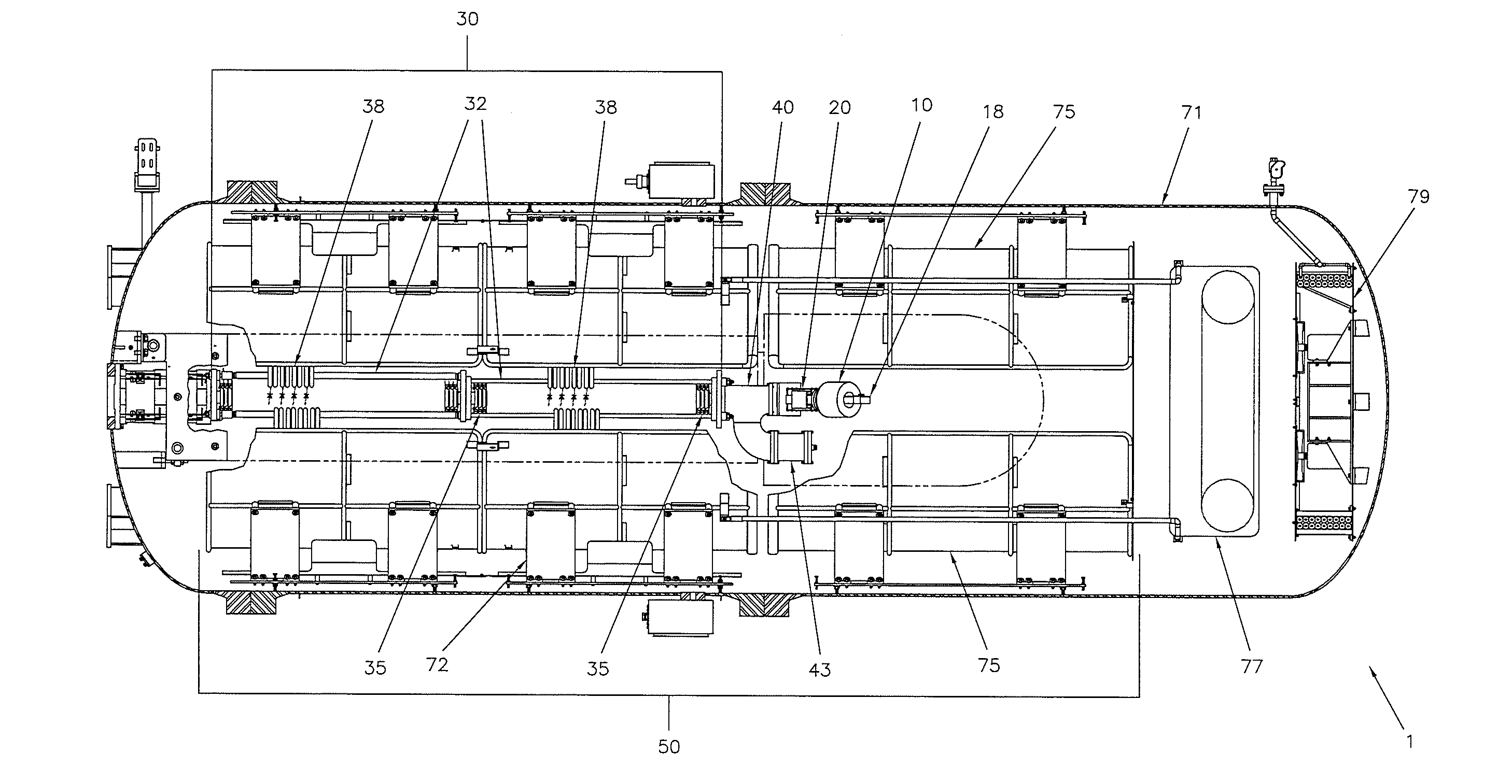
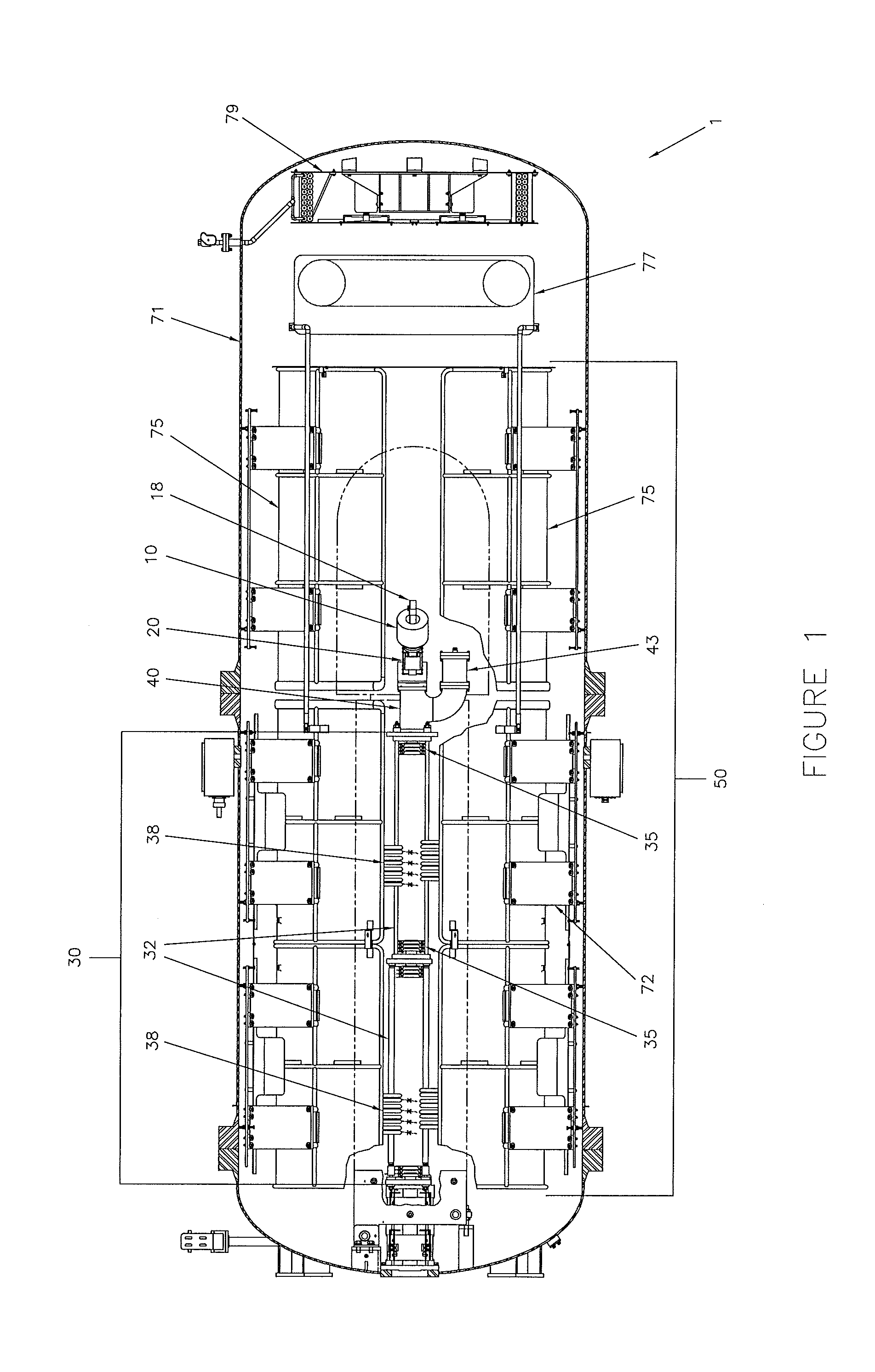
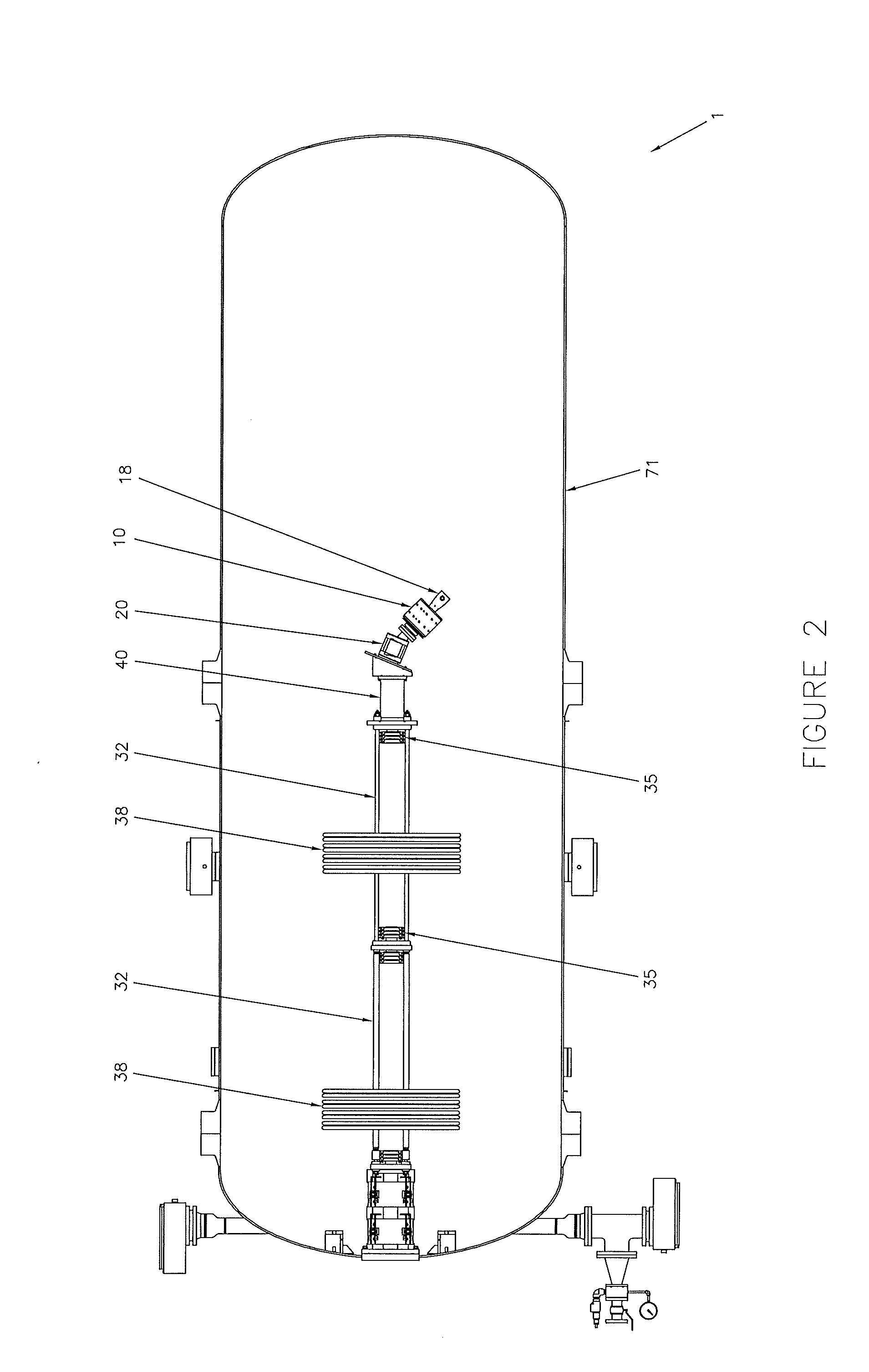
[0014]The accelerator system preferably includes components that reduce the deleterious effects of ion-gas collisions in the acceleration tube. The dipole analyzing magnet is located between the ion source and the accelerating tube. The field configuration of the analyzing magnet prevents ions other than protons produced by the ion source from reaching the accelerating tube. A vacuum sorption pump connected between the ion source and the accelerating tube may be included to reduce the amount of neutral hydrogen gas entering the accelerating tube. A small aperture may be placed at the entrance of the accelerating tube to limit the divergence of the beam to be accelerated and to further limit the amount of neutral gas entering the accelerating tube.

Problems solved by technology

However, the acceleration of a mixed beam of atomic and molecular hydrogen ions to higher energies (up to 4.5 MeV) in larger Dynamitrons was limited to only a few milliamperes.
The collisions of energetic ions with residual hydrogen gas from the ion source, which was flowing through the longer acceleration tube, had the undesirable affect of producing unfocussed hydrogen ions and free electrons.
This effect led to unstable operation at higher beam currents.
The generation of X-rays by free electrons within the acceleration tube was undesirable because it wasted high-voltage power and increased the radiation shielding requirements in the accelerator facility.
However, high-energy dc proton accelerators, capable of providing more beam current than a few milliamperes, have not been developed previously.
Despite the growing need for such an accelerator, previous attempts to develop a proton accelerator, with both high-current and high-power capabilities, have not been successful.

Method used


Image

  • High-current DC proton accelerator
  • High-current DC proton accelerator
  • High-current DC proton accelerator

Examples


Embodiment Construction

[0024]A dc accelerator system 1 able to accelerate high currents of proton beams at high energies is described. The proton beams of the invention have energies of at least about 0.3 MeV, and as high as 5 MeV at high to very high currents. At these energies, the proton accelerators produced according to the invention are able to accelerate proton beams at currents of at least about 5 mA, and as high as 100 mA while maintaining the energy of the beam.

[0025]The specific levels of the dc accelerator system 1 will depend on the intended application. For example, BNCT, energies in the range of 1.9 to 3.0 Mev are used, with beam currents of 10-20 mA. For detection of the detection of explosive materials by nuclear resonance absorption (NRA) is variable depending on the material being detected. For silicon cleaving of silicon block (for producing photovoltaic cells), currents as high as 15-25 mA, or even 30-40 mA, at energies around 4 MeV for producing thicker silicon wafers or 1 MeV or les...


PUM


Abstract

A dc accelerator system able to accelerate high currents of proton beams at high energies is provided. The accelerator system includes a dc high-voltage, high-current power supply, an evacuated ion accelerating tube, a proton ion source, a dipole analyzing magnet and a vacuum pump located in the high-voltage terminal. The high-current, high-energy dc proton beam can be directed to a number of targets depending on the applications such as boron neutron capture therapy BNCT applications, NRA applications, and silicon cleaving.

Description

CROSS-REFERENCE TO RELATED APPLICATIONS[0001]This patent application claims benefit to U.S. Provisional patent application No. 61 / 087,853, filed Aug. 11, 2008, of the same title, the entire disclosure of which is incorporated herein by reference.BACKGROUND OF THE INVENTION[0002]1. Field of the Invention[0003]The present invention relates to proton accelerators.[0004]2. Description of Related Art[0005]In the late 1920s and early 1930s, research in experimental nuclear physics was stimulated by the invention of several types of particle accelerators. These systems included the radio frequency (RF) drift-tube linear accelerator by Rolf Wideröe, the RF spiral-orbit cyclotron by Ernest Lawrence, the direct current (dc) cascaded-rectifier high-voltage generator by John Cockcroft and Ernest Walton, and the dc electrostatic high-voltage generator by Robert Van de Graaff. Approximately 600 Van de Graaff ion and electron accelerators were made by the High Voltage Engineering Corporation, whic...

Claims


Application Information

Patent Timeline
IPC IPC(8): H05H7/00
CPCH05H5/00H05H15/00H05H5/02
Inventor CLELAND, MARSHALL R.GALLOWAY, RICHARD A.DESANTO, LEONARDJONGEN, YVES
Owner ION BEAM APPL
Learn More