
Extendable deflector for discharging structure-damaging fluids

Active Publication Date: 2010-02-11
AIRBUS OPERATIONS GMBH
View PDF12 Cites 22 Cited by
  • Summary
  • Abstract
  • Description
  • Claims
  • Application Information

AI Technical Summary

Benefits of technology

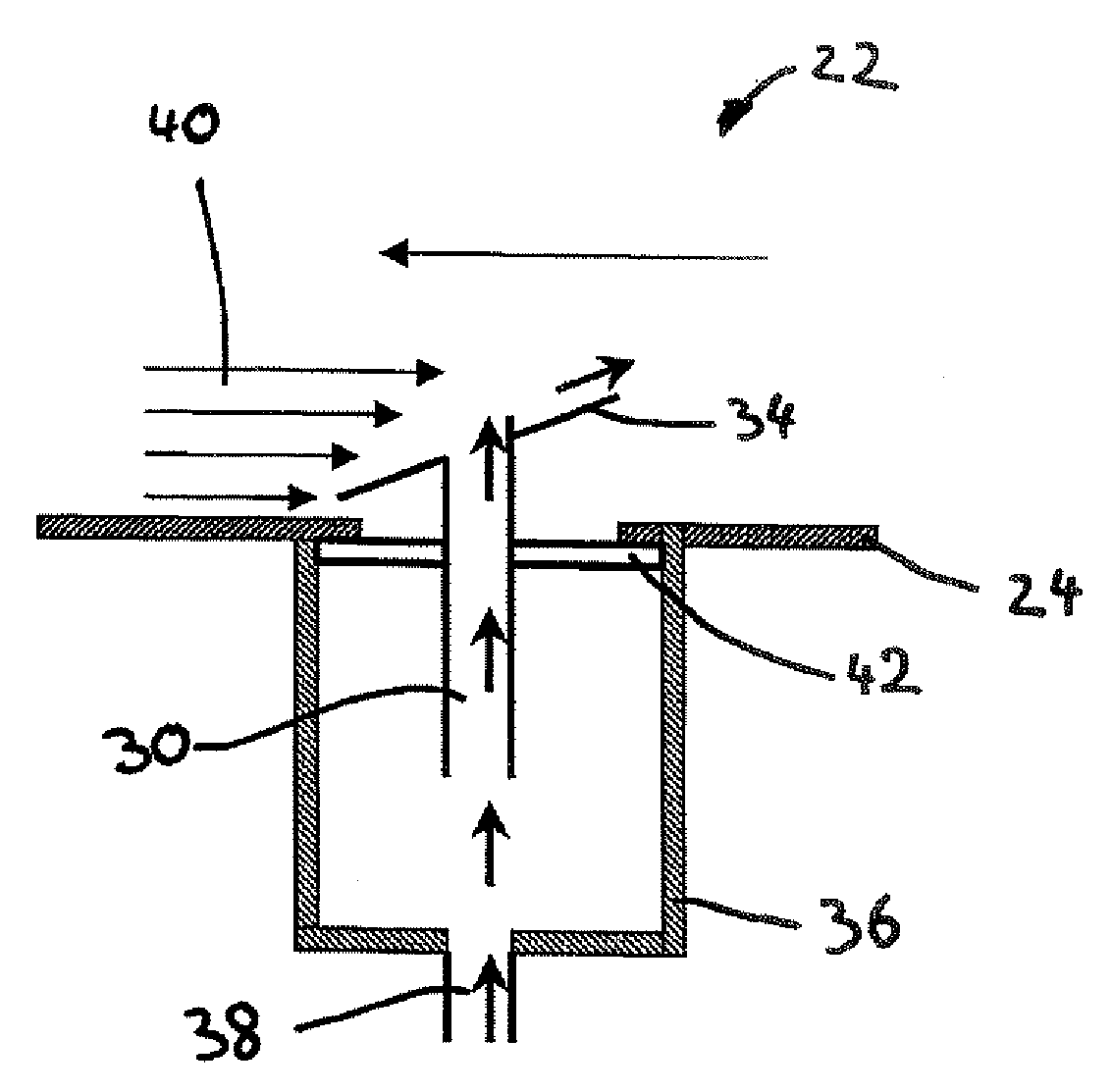
[0011]It may therefore be an object of the invention to propose a deflector for discharging fluids from an aircraft, which deflector when required removes the fluids to be discharged as safely as possible away from the exterior structure of the aircraft without permanently increasing the flow resistance of the aircraft.

Problems solved by technology

This design does not increase the aerodynamic resistance of the aircraft in the normal situation.

Method used


Image

  • Extendable deflector for discharging structure-damaging fluids
  • Extendable deflector for discharging structure-damaging fluids
  • Extendable deflector for discharging structure-damaging fluids

Examples


Embodiment Construction

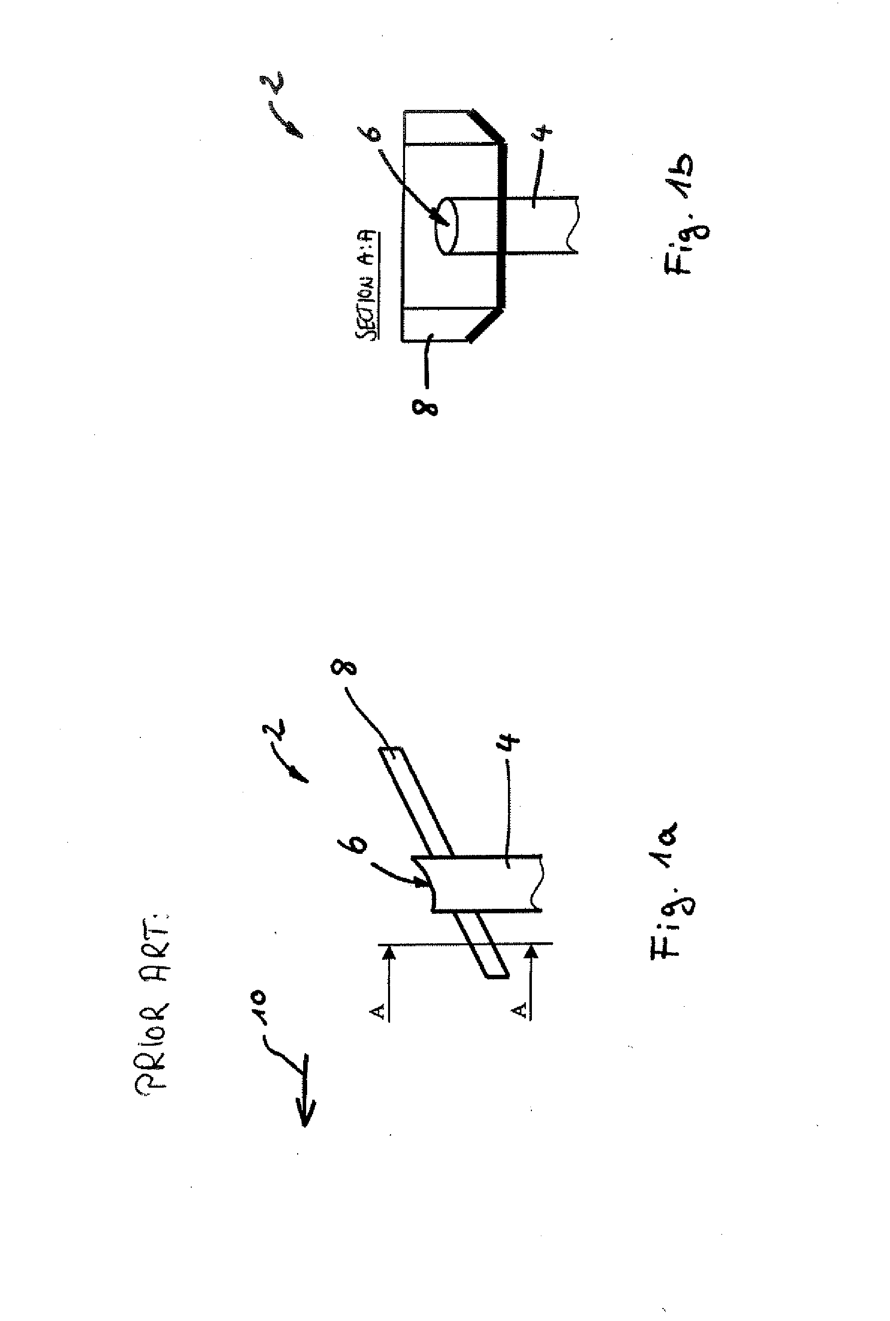
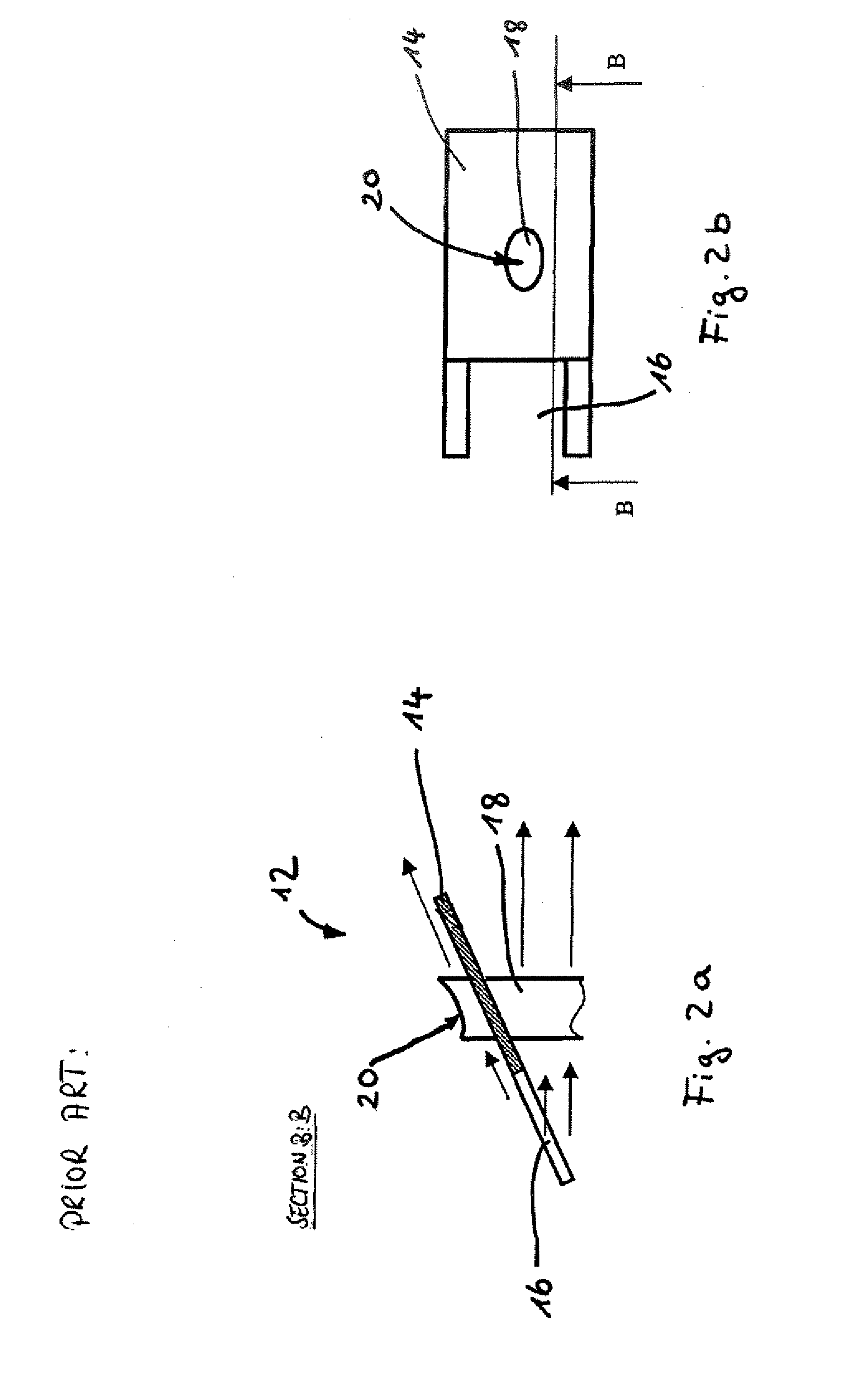
[0043]FIGS. 1a to 2b show a deflector 2 from the state of the art, which deflector 2 may nor be extended. Consequently, the deflector 2 permanently causes an increase in the aerodynamic resistance of the aircraft. The deflector 2 comprises a discharge pipe 4 at the outlet end 6 of which a guiding plate 8 is arranged that is aligned obliquely relative to the exterior skin (not shown) of the aircraft. The fluid to be discharged is guided through the discharge pipe to the outlet end 6, from which it may exit to the environment of the aircraft. If the aircraft's airflow that results in flight extends from the left to the right in the drawing plane, as indicated by the direction of flight 10 that goes against the former, the fluid discharged from the discharge pipe 4 at its outlet end 6 is taken along by the air flow and is guided obliquely away from the outlet end 6, wherein the guiding plate 8 imparts to the fluid a speed component parallel to the discharge pipe 4.

[0044]FIGS. 2a and 2b...


PUM


Abstract

The invention relates to a deflector for an aircraft, comprising a discharge pipe for leading a fluid to be drained from the aircraft by way of an outlet end to the environment of the aircraft; an actuator, coupled to the discharge pipe, for swinging out, when required, the discharge pipe to at least one activation position, wherein in the activation position the outlet end is arranged so as to be spaced apart from the exterior skin of the aircraft, and the deflector guides the fluid to be drained so that it exits outside a flow boundary layer that is present on the exterior skin. The deflector according to the invention is activated when required and is able to discharge structure-damaging fluids to the environment in such a way that the exterior structure of the aircraft does not become wet, and at the same time the deflector according to the invention, normally accommodated within the contour of the aircraft, does not result in any additional aerodynamic resistance.

Description

CROSS-REFERENCE TO RELATED APPLICATIONS[0001]This application claims the benefit of the filing date of U.S. Provisional Patent Application No. 61 / 188,408 filed Aug. 8, 2008, the disclosure of which is hereby incorporated herein by reference.BACKGROUND OF THE INVENTION[0002]The invention relates to a deflector for an aircraft, to the use of a deflector in an aircraft, and to a method for discharging fluids from an aircraft to the environment of the aircraft.[0003]Hereinafter, the term “deflector” refers to devices and arrangements that are designed to discharge fluids from the interior of an aircraft to the environment. It is well known that fluids may be discharged by way of an outlet of an aircraft, wherein such an outlet is positioned so as to be flush with the exterior skin of the aircraft. Optionally, the outlet may be closed by means of a blind plug, wherein the blind plug may be pushed out as a result of the pressure of the discharging fluid. However, in the case of an outlet ...

Claims


Application Information

Patent Timeline
IPC IPC(8): B64D1/16
CPCB64C1/1453B64D37/26B64D1/16
Inventor PIESKER, MARKUS
Owner AIRBUS OPERATIONS GMBH
Learn More