
Magnetic carrier and two-component developer

a technology of magnetic carrier and developer, applied in the field of magnetic carrier and two-component developer, can solve the problems of no improvement in carrier adhesion and ratio durability, and achieve the effects of reducing carrier adhesion, reducing fogging, and reducing coarseness of toner images

Inactive Publication Date: 2010-02-04
CANON KK
View PDF21 Cites 71 Cited by
  • Summary
  • Abstract
  • Description
  • Claims
  • Application Information

AI Technical Summary

Benefits of technology

The present invention relates to a magnetic carrier and a two-component developer that can improve the quality of toner images and reduce issues such as coarseness and fogging when printing after being exposed to high temperatures and humidity environments. Additionally, the invention can alleviate blank areas in low humidity environments. The technical effects of the invention are achieved by controlling the pore diameter distribution of porous magnetic core particles used in the magnetic carrier.

Problems solved by technology

In addition, when 50,000 sheets were printed out in a low image ratio (an image ratio of 1%), and a damaged magnetic carrier was adhered onto the image in some cases.
However, no improvement was made for the carrier adhesion after a low image ratio durability test, the fogging after being allowed to stand in a high temperature and high humidity environment and the Blank areas in a low humidity environment by only defining and controlling the ratio between the total volume of the pores and the total volume of the pores and voids and the void diameter, as described above.

Method used


Image

  • Magnetic carrier and two-component developer
  • Magnetic carrier and two-component developer
  • Magnetic carrier and two-component developer

Examples


production example 2

of Porous Magnetic Core Particles

[0256]In the Production Example 1 of the porous magnetic core particles, the pulverizing time in the wet-type beads mill in Step 3 was changed to 2 hours. The resulting pulverized product of the preliminarily calcined ferrite has D50 of 1.4 μm and D90 of 3.0 μm. In addition, the calcination temperature in Step 5 was changed from 1050° C. to 1100° C. Except for the above, porous magnetic core particles 2 were obtained in the same manner as in Production Example 1 of the porous magnetic core particles.

production example 3

of Porous Magnetic Core Particles

[0257]In the Production Example 1 of the porous magnetic core particles, the pulverizing time of the wet-type beads mill in Step 3 was changed from 3 hours to 2 hours. The resulting pulverized product of the preliminarily calcined ferrite has D50 of 1.7 μm and D90 of 5.0 μm. In addition, the calcination temperature in Step 5 was changed from 1050° C. to 1150° C. Except for the above, porous magnetic core particles 3 were obtained in the same manner as in Production Example 1 of the porous magnetic core particles.

production example 4

of Porous Magnetic Core Particles

[0258]In the Production Example 1 of the porous magnetic core particles, the pulverization particle size by a crusher in Step 3 was changed from approximately 0.5 mm to approximately 0.3 mm, the balls of the wet-type ball mill was changed from balls (a diameter of 10 mm) made of zirconia to balls (a diameter of 10 mm) made of stainless steel, and the pulverizing time of the wet-type beads mill was changed from 3 hours to one hour in Step 3. The resulting pulverized product of the preliminarily calcined ferrite has D50 of 2.1 μm and D90 of 6.3 μm. In addition, the calcination temperature in Step 5 was changed from 1050° C. to 1100° C. Except for the above, porous magnetic core particles 4 were obtained in the same manner as in Production Example 1 of the porous magnetic core particles.

Production Example 5 of Porous Magnetic Core Particles

[0259]In the Production Example 1 of the porous magnetic core particles, the balls of the wet-type ball mill in Ste...


PUM


Abstract

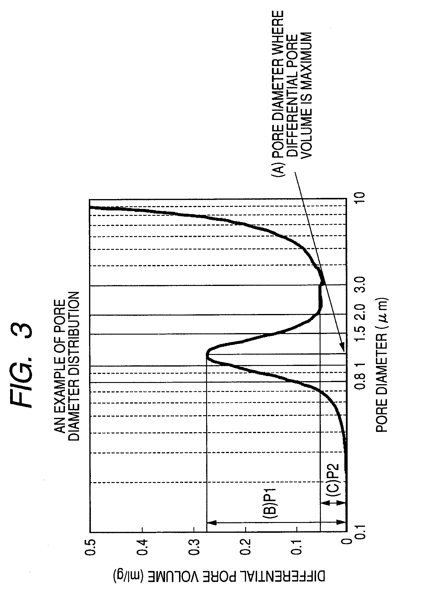
A magnetic carrier and two-component developer are provided alleviating coarse images, fogging when printing is done after a copier body is left standing for one week in a high temperature and high humidity environment and carrier adhesion after extensive operation in a low image ratio. The magnetic carrier includes magnetic carrier particles including porous magnetic core particles and a resin, wherein in a mercury intrusion method applied to the porous magnetic core particles, a pore diameter in which a differential pore volume in the specific pore diameter range becomes maximum is in a specific range, and when the maximum value of a differential pore volume in the specific pore diameter range is defined as P1 and the maximum value of a differential pore volume in the specific pore diameter range is defined as P2, P1 is in a specific range and the ratio P2 / P1 is in a specific range.

Description

BACKGROUND OF THE INVENTION[0001]1. Field of the Invention[0002]The present invention relates to a magnetic carrier and a two-component developer used for an electrophotographic method and an electrostatic recording method.[0003]2. Description of the Related Art[0004]In an electrophotographic method, a step of developing an electrostatic image forms a toner image and attaches a frictionally charged toner onto the electrostatic image using coulomb force with the electrostatic image. The developer for developing the electrostatic image using the toner includes a one-component developer using a magnetic toner obtained by dispersing a magnetic material in a resin and a two-component developer which is used by mixing a non-magnetic toner with a magnetic carrier.[0005]The latter is preferably used especially for a full-color copying machine for which high image quality is demanded or a full-color image forming apparatus such as a full-color printer.[0006]Recently, also in a full-color ima...

Claims


Application Information

Patent Timeline
Patent Type & Authority Applications(United States)
IPC IPC(8): G03G9/08G03G9/107G03G9/113
CPCG03G9/1136G03G9/1075
Inventor NAKAMURA, KUNIHIKOFUJIKAWA, HIROYUKIISHIGAMI, KOHKOMATSU, NOZOMUINOUE, CHIKAENDO, TOMOKOBABA, YOSHINOBUITAKURA, TAKAYUKI
Owner CANON KK
Learn More