
High Strength Spring Steel and High Strength Heat Treated Steel Wire for Spring

a high-tensile steel wire and spring technology, applied in the field of high-tensile spring steel and high-tensile heat treatment steel wire for springs, can solve the problems of not being able to form into a spring shape, coilability and workability cannot be obtained simultaneously, etc., to achieve high strength and coilability, secure toughness and workability, and suppress formation

Inactive Publication Date: 2010-02-04
NIPPON STEEL & SUMITOMO METAL CORP
View PDF3 Cites 19 Cited by
  • Summary
  • Abstract
  • Description
  • Claims
  • Application Information

AI Technical Summary

Benefits of technology

[0010]The inventors discovered that by controlling the N, which was not focused on until now, even if adding alloy elements, it is possible to suppress the formation of undissolved carbides and possible to secure toughness and workability and thereby developed a heat treated steel wire for a spring achieving both a high strength and coilability. That is, the gist of the present invention is as follows.

Problems solved by technology

However, if the steel wire for a cold-coiled spring increases in strength, it often breaks during cold coiling and cannot be formed into a spring shape.
Up until now, both strength and workability (coilability) could not be simultaneously obtained with this, so strength and workability had to be obtained by what may be said to be the industrially disadvantageous techniques of hot coiling or quenching and tempering after hot coiling.
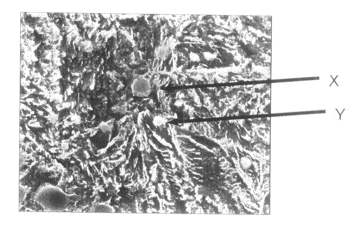
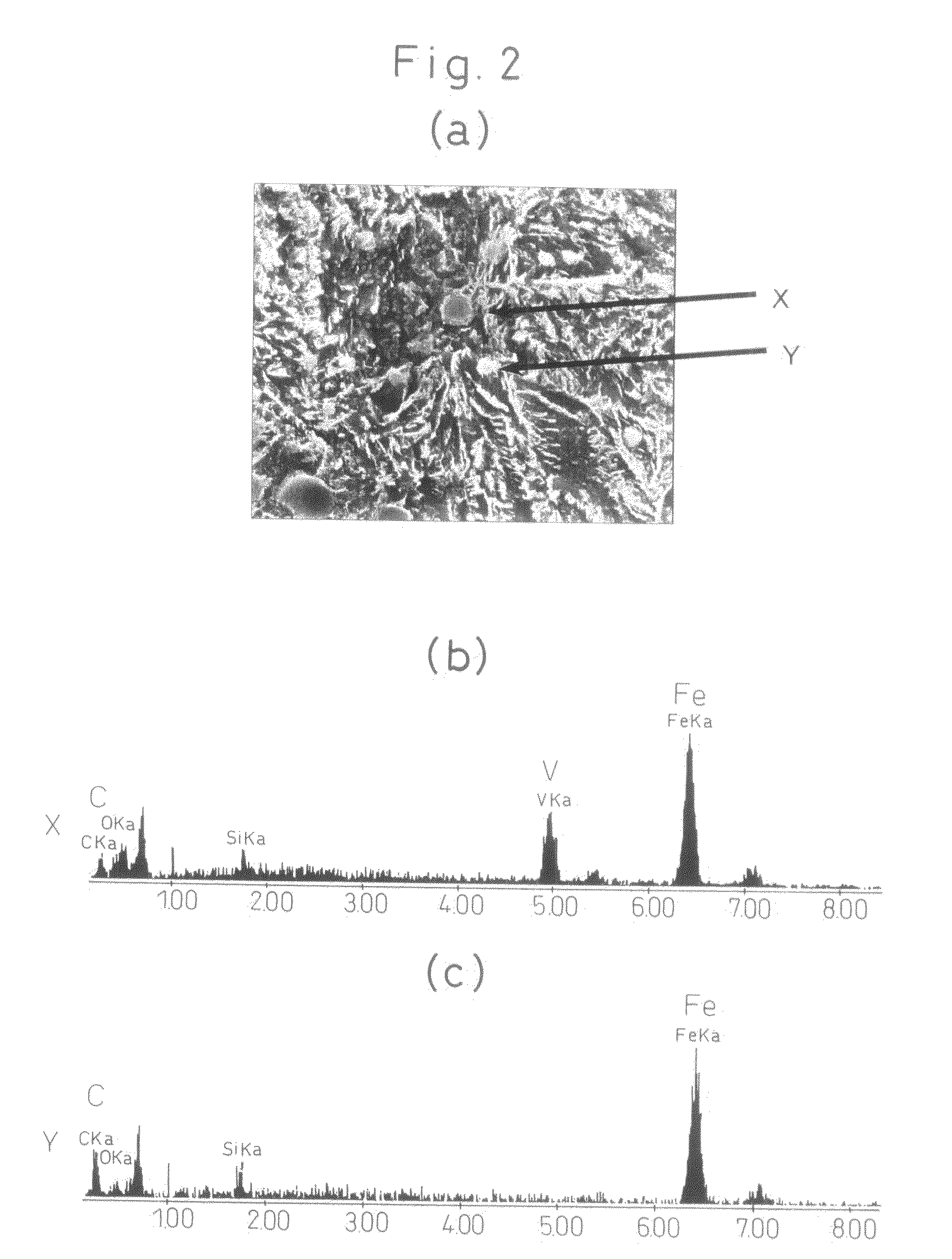
However, if adding a large amount of such elements is added, it will not be able to dissolve by the heating of the quenching and will grow to coarse grains resulting in so-called undissolved carbides causing breakage at the time of cold coiling.

Method used


Image

  • High Strength Spring Steel and High Strength Heat Treated Steel Wire for Spring
  • High Strength Spring Steel and High Strength Heat Treated Steel Wire for Spring
  • High Strength Spring Steel and High Strength Heat Treated Steel Wire for Spring

Examples


examples

Evaluation Items

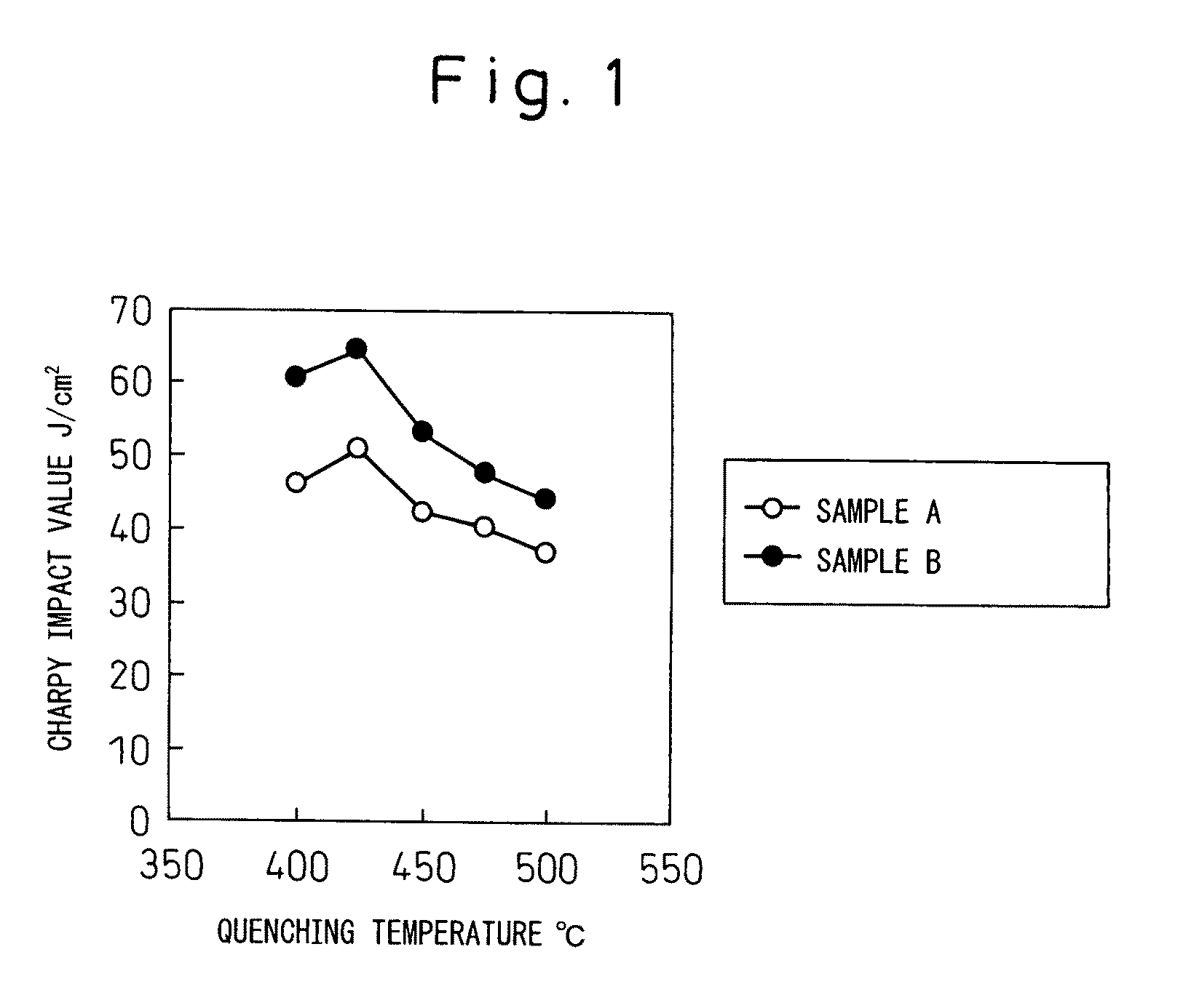
[0087]To evaluate the applicability of the present invention to a spring, the tensile strength, hardness after annealing, impact value, and reduction in area as measured by a tensile test are shown as evaluation items. The tensile strength is directly linked with the fatigue limit of the spring. The higher the strength, the higher the fatigue limit shown.

[0088]Further, the reduction in area measured simultaneously with the measurement of the tensile strength shows the plastic deformation behavior of the material and is an evaluation indicator of workability into a spring (coiling characteristic). The larger the reduction in area, the easier workability shown, but in general the higher the strength, the smaller the reduction in area. From the examples of conventional steel, if the reduction in area exceeds 30% evaluated by this wire diameter, it is learned that problems will not easily occur in industrial scale mass production even with other wire diameters. The prepa...


PUM

PropertyMeasurementUnit
Lengthaaaaaaaaaa
Fractionaaaaaaaaaa
Fractionaaaaaaaaaa

Abstract

The present invention provides a high strength heat treated steel wire for spring having a tensile strength of 2000 MPa or more which is coiled in the cold state and can achieve both sufficient atmospheric strength and coilability and spring steel used for that steel wire, that is, a high strength heat treated steel wire for a spring characterized by comprising, by mass %, C: 0.5 to 0.9%, Si: 1.0 to 3.0%, Mn: 0.1 to 1.5%, Cr: 1.0 to 2.5%, V: over 0.15 to 1.0%, and Al: 0.005% or less, controlling N to 0.007% or less, further containing one or two of Nb: 0.001 to less than 0.01% and Ti: 0.001 to less 0.005%, and having a tensile strength of 2000 MPa or more, having cementite-based spheroidal carbides and alloy-based spheroidal carbides in a microscopic visual field satisfying an area percentage of carbides with a circle equivalent diameter of 0.2 μm or more of 7% or less and a density of carbides with a circle equivalent diameter of 1 grain / μm2 or less, having a prior austenite grain size number of #10 or more, and having retained austenite of 15 mass % or less.

Description

TECHNICAL FIELD[0001]The present invention relates to spring steel which is cold-coiled and has a high strength and high toughness and to heat treated steel wire for a spring.BACKGROUND ART[0002]Due to trends toward weight reduction and higher performance of automobiles, springs have been strengthened and high strength steel having a tensile strength in excess of 1500 MPa after heat treatment has been applied to springs. In recent years, steel wire having a tensile strength in excess of 1900 MPa has also been demanded. The purpose is to secure a material hardness which does not cause problems when the material is used as a spring even though the material softens to some extent by heating in strain reduction annealing, nitriding, and the like when producing the spring.[0003]Further, by nitriding and shot-peening, it is known that the surface layer hardness increases and the durability in spring fatigue is remarkably improved, but the characteristics in the spring are not decided by s...

Claims


Application Information

Patent Timeline
IPC IPC(8): C22C38/22C22C38/04C22C38/20C22C38/24C22C38/26C22C38/60C22C38/44C22C38/46C22C38/48C22C38/50
CPCC22C38/02C22C38/24C22C38/04
Inventor HASHIMURA, MASAYUKIHAGIWARA, HIROSHIKISU, TAKAYUKIYAMAZAKI, KOUICHIOCHI, TATSUROIFUJITA, TAKASHI
Owner NIPPON STEEL & SUMITOMO METAL CORP
Learn More