
Electric vehicle thermal management system

a technology for thermal management systems and electric vehicles, applied in ventilation systems, lighting and heating apparatuses, heating types, etc., can solve problems such as and inability to meet the needs of electric vehicles

Active Publication Date: 2010-02-04
TESLA INC
View PDF32 Cites 65 Cited by
  • Summary
  • Abstract
  • Description
  • Claims
  • Application Information

AI Technical Summary

Benefits of technology

The present invention provides a method for managing thermal loads in an electric vehicle. The method involves cooling a heat exchanger with a refrigeration system, circulating a coolant looped to the heat exchanger and the vehicle's energy storage system, and another coolant looped to the vehicle's HVAC subsystem. The method may also involve circulating a coolant looped to the vehicle's drive motor and using a radiator to pass air into the passenger cabin. The flow rate of the coolants can be controlled using valves or circulation pumps. The technical effect of this invention is to efficiently manage the temperature of the electric vehicle, which can improve its performance and comfort.

Problems solved by technology

The use of such vehicles, more specifically the use of vehicles which rely on fossil fuels, i.e., gasoline, creates two problems.
First, due to the finite size and limited regional availability of such fuels, major price fluctuations and a generally upward pricing trend in the cost of gasoline are common, both of which can have a dramatic impact at the consumer level.
One of the principal issues involved in designing an efficient electric drive train as well as a vehicle that is “user friendly” is thermal management, primarily due to the required operating conditions of the battery cells and the need to provide on-demand heating and cooling within the passenger cabin.
To date, electric vehicle thermal management systems have had limited capabilities, been overly complex, or both.
Such an approach is inherently inefficient as each heat management subsystem requires its own components (e.g., pumps, valves, refrigerant systems, etc.).
Although this system appears to overcome some of the limitations of the prior systems, it is still relatively complex due to the interaction of the two heat transfer circuits.

Method used


Image

  • Electric vehicle thermal management system
  • Electric vehicle thermal management system

Examples


Embodiment Construction

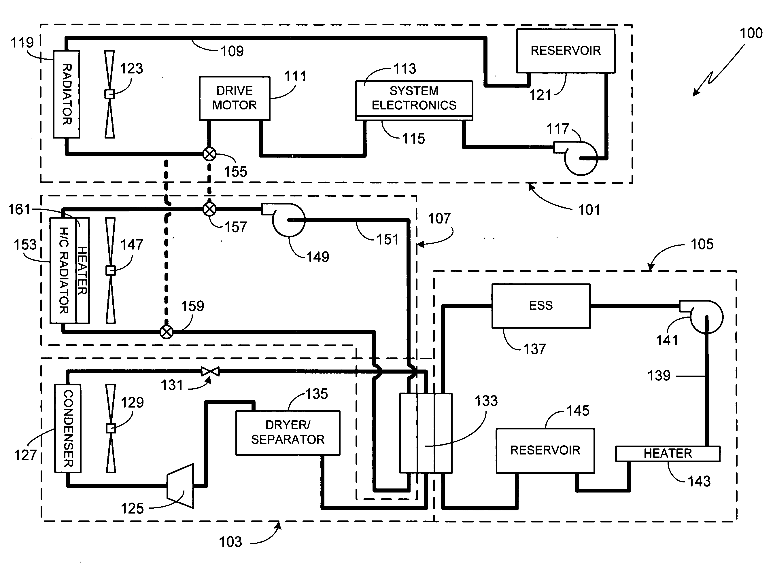
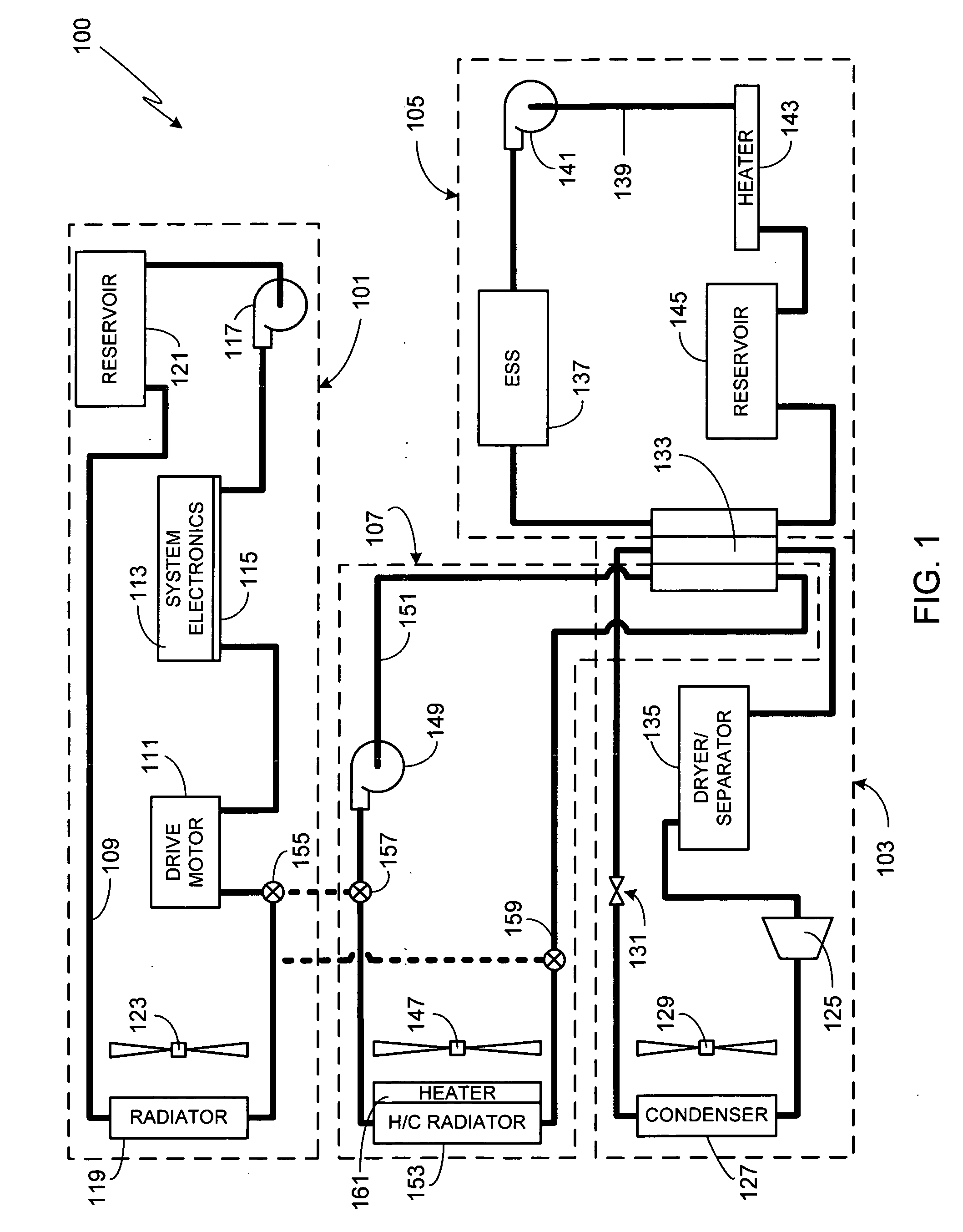
[0010]FIG. 1 schematically illustrates a thermal management system 100 in accordance with a preferred embodiment of the invention. System 100 is comprised of four subsystems; power train cooling subsystem 101, refrigeration subsystem 103, battery cooling subsystem 105, and heating, ventilation and cooling (HVAC) subsystem 107. Each subsystem will now be described in detail.

[0011]Subsystem 101 is comprised of a continuous power train cooling loop 109 which is used to cool drive motor 111, the vehicle's principal traction motor. Preferably cooling loop 109 is also used to cool various system electronic components 113 (e.g., the power electronics module for motor 109). System electronics 113 are preferably mounted to a cold plate 115 which is used to transfer the heat away from the electronics and into the liquid coolant (i.e., the heat transfer medium) contained in the cooling loop. Cooling loop 109 also includes a pump 117 to circulate the coolant through the cooling loop, a radiator...


PUM


Abstract

A method for managing thermal loads within an electric vehicle using an efficient thermal management system (100) that utilizes a single heat exchanger (133) is provided. A refrigeration subsystem (103) cools the heat exchanger (133). A first coolant loop (139) in thermal communication with the heat exchanger (133) is used to cool the energy storage system (137). A second coolant loop (151) corresponding to the HVAC subsystem (107) is also in thermal communication with the heat exchanger (133). Preferably a third coolant loop (109) corresponding to the drive motor cooling subsystem (101) is coupleable to the HVAC coolant loop (151), thus providing an efficient means of providing heat to the HVAC subsystem (107).

Description

CROSS-REFERENCES TO RELATED APPLICATIONS[0001]This application is a divisional of U.S. patent application Ser. No. 11 / 786,108, filed Apr. 11, 2007, the disclosure of which is incorporated herein by reference for any and all purposes.FIELD OF THE INVENTION[0002]The present invention relates generally to electric vehicles and, more particularly, to a method and apparatus for efficiently managing the thermal loads in an electric vehicle.BACKGROUND OF THE INVENTION[0003]An extremely large percentage of the world's vehicles run on gasoline using an internal combustion engine. The use of such vehicles, more specifically the use of vehicles which rely on fossil fuels, i.e., gasoline, creates two problems. First, due to the finite size and limited regional availability of such fuels, major price fluctuations and a generally upward pricing trend in the cost of gasoline are common, both of which can have a dramatic impact at the consumer level. Second, fossil fuel combustion is one of the pri...

Claims


Application Information

Patent Timeline
Patent Type & Authority Applications(United States)
IPC IPC(8): B60H1/00F28D15/00B60H1/32F24F7/00
CPCB60H1/00278Y02T10/7291B60H1/00885B60H2001/00307B60H2001/00928B60L1/003B60L1/02B60L3/003B60L11/1803B60L11/1874B60L11/1875B60L2240/34B60L2240/36B60L2240/545B60L2240/662Y02T10/7005Y02T10/705Y02T90/16B60H1/00392B60L50/51B60L58/26B60L58/27B60H1/32281Y02T10/70Y02T10/72
Inventor ZHOU, PENG
Owner TESLA INC
Learn More