
Low Nox Swirl Coal Combustion Burner

Inactive Publication Date: 2010-01-28
HARBIN INST OF TECH
View PDF9 Cites 18 Cited by
  • Summary
  • Abstract
  • Description
  • Claims
  • Application Information

AI Technical Summary

Benefits of technology

[0005]A main object of the present invention is to provide a low NOx swirl coal combustion burner, which can solve the problem of the conventional CFR swirl coal combustion burner being ineffectively inhibited the formation of fuel-NOx.
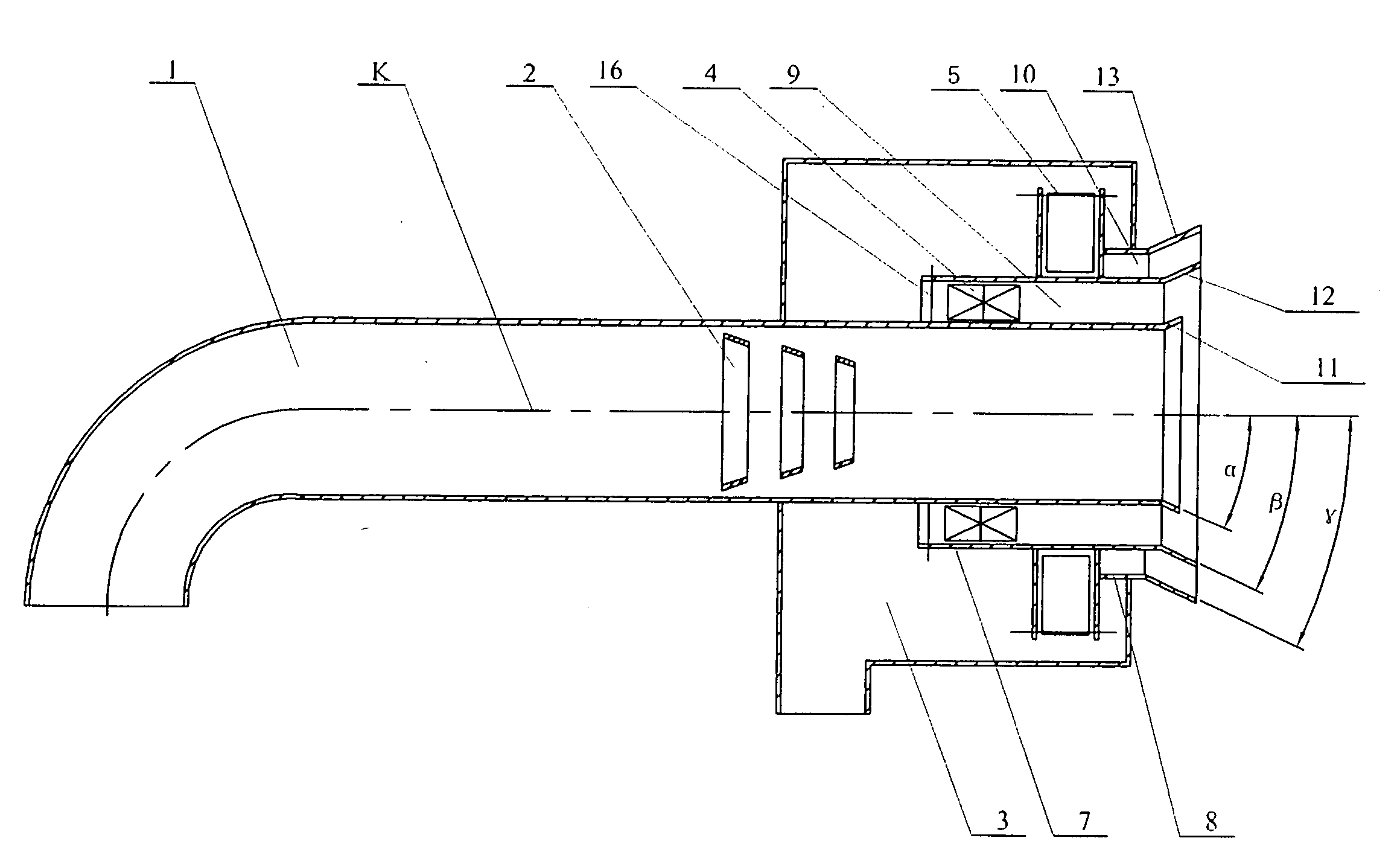
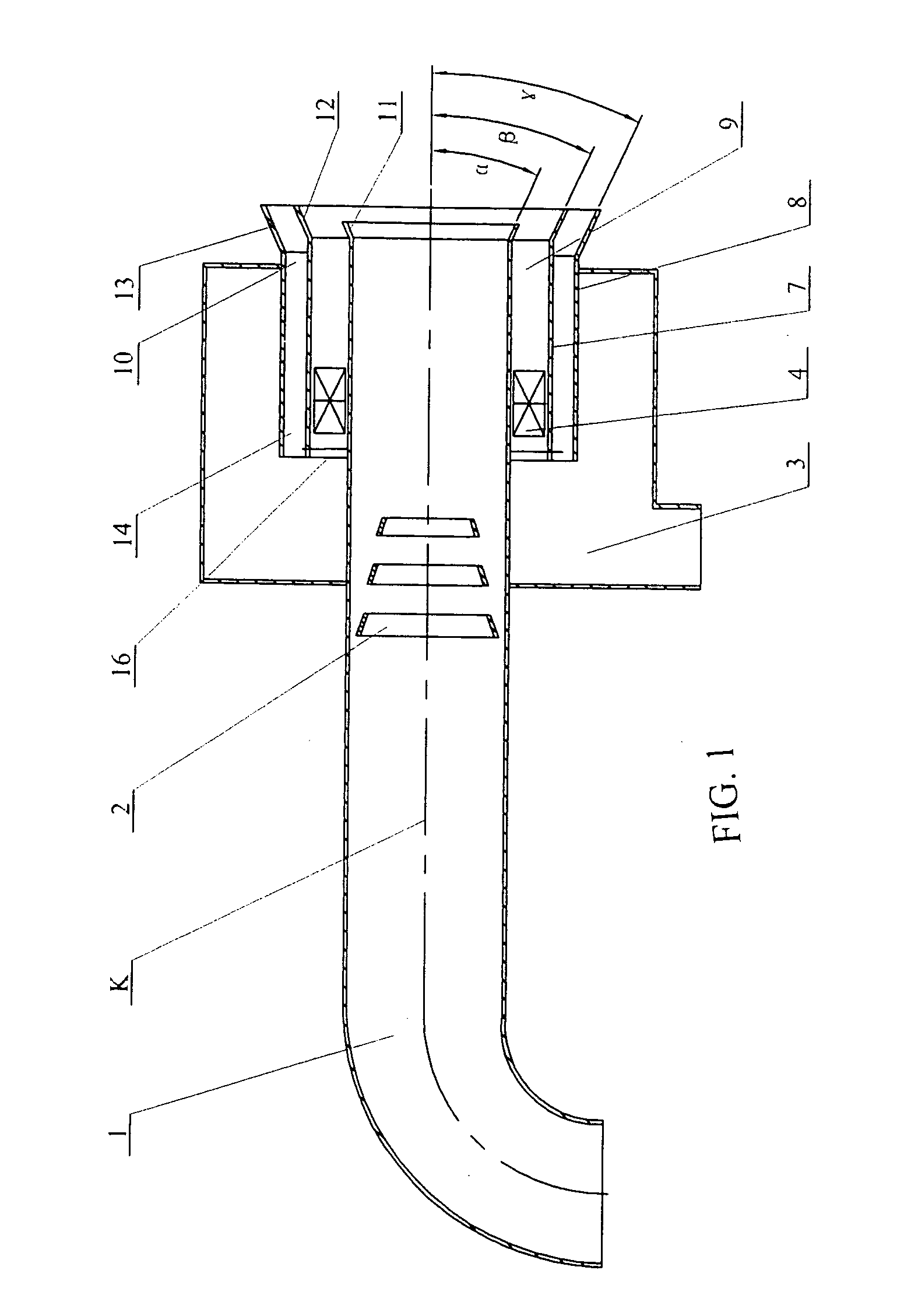
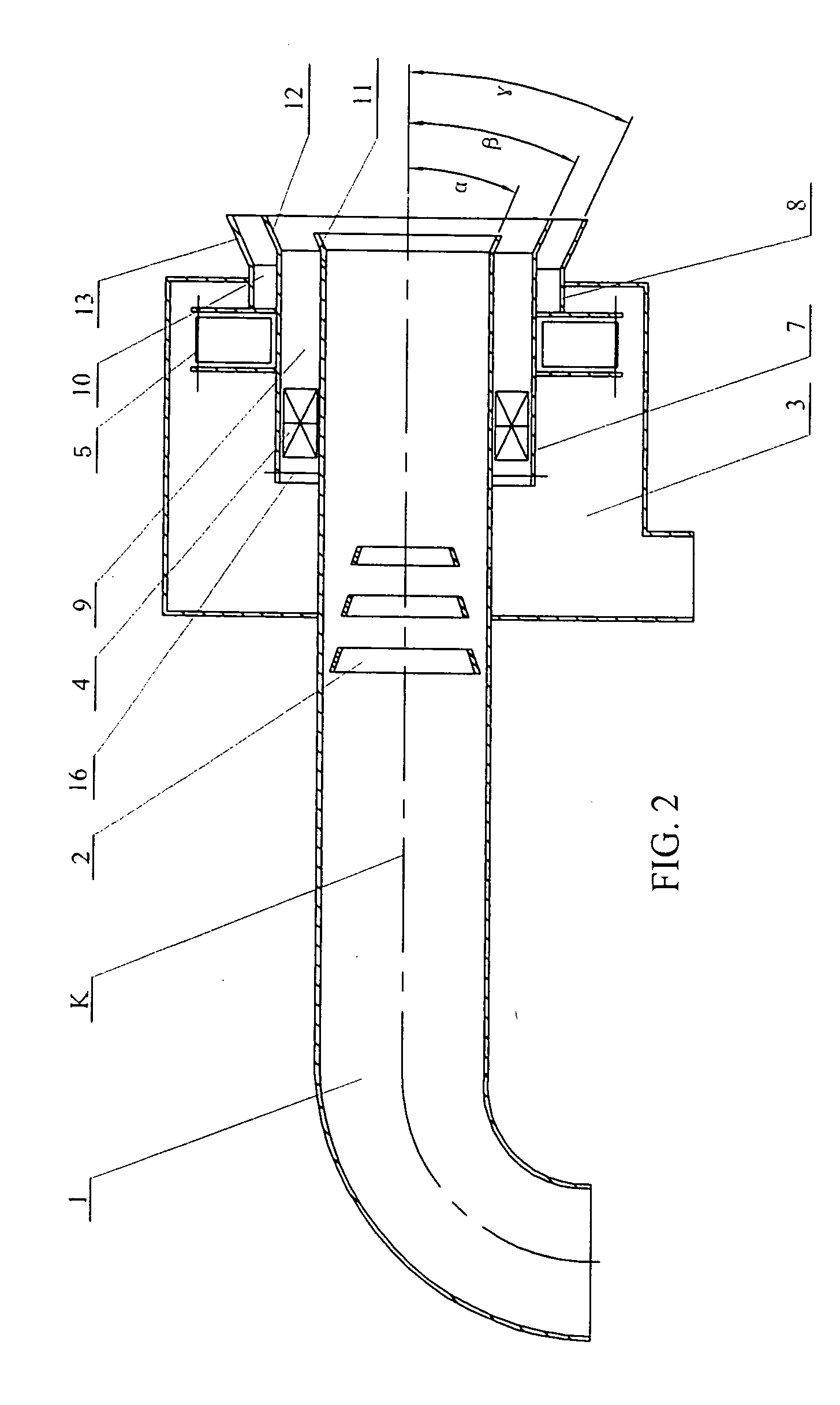
[0008]The secondary air flow is partitioned into two portions into the furnace through the inner and outer secondary air ducts, wherein the inner and outer secondary air vanes are arranged to regulate the two portions of the secondary air flow in a swirling manner at the inner secondary air duct and the outer secondary air duct respectively. Under the effects of the primary air-coal mixture conical outlet, the inner secondary air conical outlet, and the outer secondary air conical outlet, the flow of air-coal mixture at the primary air-coal mixture duct is mixed with the swirling air flow at the inner and outer secondary air ducts to form a moderate central recirculation zone. In addition, the burner of the present invention does not include any central duct. The primary air-coal mixture duct is located at a center of the burner, wherein the primary air-coal mixture flow is formed in a non-swirling manner that the primary air-coal mixture flow is straight-forwardly passing through the primary air-coal mixture duct. One or more pulverized coal separators are coaxially supported within the primary air-coal mixture duct along the centerline thereof to inject the flow of air-coal mixture at the center of primary air-coal mixture duct into the furnace, so as to increase the amount of the pulverized coal at the central recirculation zone, to enhance the reduction ability of the air-coal mixture at the central recirculation zone, and to prolong the residence time of the air-coal mixture at the center recirculation zone for effectively reducing the formation of NOx. The conical outlets are arranged to delay the mixing time of the primary air-coal mixture and secondary air flows through the primary air-coal mixture and inner and outer secondary air ducts and to further prolong the residence time in the center recirculation zone under the reduction ability so as to effectively reduce the formation of NOx. Accordingly, the secondary air flow is partitioned into two portions for being transversely injected into the furnace. The inner portion of the secondary air flow is used as an igniter for igniting the pulverized coal. The outer portion of the secondary air flow is used as an oxygen suppler for supplying enough oxygen for complete combustion of the pulverized coal, so as to inhibit the formation of NOx. The staged mixing manner of the secondary air flow at the radial direction has an advantage of reducing the emission of NOx.

Problems solved by technology

It not only forms the acid rain to damage the ecological environment, but also forms the actinic fog to harm the health of human being.
However, there is no conical outlet installed at the outlets of the primary air-coal mixture, inner and outer secondary air ducts, the pulverized coal at the primary air-coal mixture and inner and outer secondary air ducts is parallelly spurted into the furnace so that the central recirculation zone formed by the swirl of the secondary air is relatively small.
Thus, the residence time of pulverized coal in the central recirculation is not long enough to inhibit the formation of nitrogen oxide compound at most.
Therefore, it cannot effectively inhibit the formation of NOx.
Furthermore, the major drawbacks of the second method of controlling the nitrogen oxide compound, through the flue gas denitrification by applying removing reactant of denitrification to flue gas to remove nitrogen oxide compound, are high investment cost and operating cost.

Method used


Image

  • Low Nox Swirl Coal Combustion Burner
  • Low Nox Swirl Coal Combustion Burner
  • Low Nox Swirl Coal Combustion Burner

Examples


Embodiment Construction

[0016]Referring to FIGS. 1 and 2 of the drawings, a low NOx swirl coal combustion burner according to a preferred embodiment of the present invention is illustrated, wherein the low NOx swirl coal combustion burner comprises a primary air-coal mixture duct 1, a conical pulverized coal separator 2, a secondary air wind box 3, an inner secondary air vane 4, a primary air-coal mixture conical outlet 11, an inner secondary air conical outlet 12, and an outer secondary air conical outlet 13.

[0017]The primary air-coal mixture duct 1 is coaxially extended through the secondary air wind box 3, wherein the pulverized coal separator 2 is supported within the primary air-coal mixture duct 1. An outlet of the pulverized coal separator 2, which is an opening having a smaller diameter, is alignedly pointing towards an outlet of the primary air-coal mixture duct 1. Inner and outer tubular sleeves 7, 8 are encirclingly coupled with the primary air-coal mixture duct 1 to form an inner secondary air ...


PUM


Abstract

A burner includes a primary air-coal mixture duct coaxially extended through a secondary air wind box, a pulverized coal separator supported within the primary air-coal mixture duct, a secondary air duct including an inner secondary air duct and an outer secondary air duct coaxially formed around the primary air-coal mixture duct, a primary air-coal mixture conical outlet coupled with the outlet of the primary air-coal mixture duct, and inner secondary air and outer conical outlets coupled with the outlets of the inner secondary air and outer secondary air ducts respectively. The conical outlets are arranged to delay the mixing time of the primary air-coal mixture and secondary air flows through the primary air-coal mixture and secondary air ducts and to prolong the residence time in the center recirculation zone under the reduction ability so as to effectively reduce the formation of NOx.

Description

BACKGROUND OF THE PRESENT INVENTION[0001]1. Field of Invention[0002]The present invention relates to a burner, and more specifically to a centrally fuel rich (CFR) swirl coal combustion burner which can reduce the output of the emissions amount of NOx.[0003]2. Description of Related Arts[0004]Nitrogen Oxide (NOx) is one of the main contaminants for air pollution. It not only forms the acid rain to damage the ecological environment, but also forms the actinic fog to harm the health of human being. The coal combustion is one of the main sources of the generation of nitrogen oxide compound. At the present, there are two methods to control the formation of NOx. The first method is low NOx combustion technology which can reduce the formation of NOx. The second method is the flue gas denitrification which applies removing reactant of denitrification to the flue gas to remove NOx. China Patent, CN1207511C, publication date of Jun. 22, 2005, entitled “Centrally Fuel Rich (CFR) Swirl Coal Co...

Claims


Application Information

Patent Timeline
IPC IPC(8): F23D1/02
CPCF23D1/00F23D2201/20F23D2201/10F23D1/02
Inventor LI, ZHENGGICHEN, ZHICHAOSUN, RUISUN, SHAOZENGWU, SHAOHUAQIN, MINGQIN, YUNKUN
Owner HARBIN INST OF TECH
Learn More