High Voltage Discharge Lamp Lighting Device

a lighting device and high-voltage discharge technology, which is applied in the direction of electric variable regulation, process and machine control, instruments, etc., can solve the problems of increased size and cost of lighting devices, inability to start lamps, and possibility of leakage in wiring or sockets, so as to improve construction ease and simplify the structure of detection circuits

Inactive Publication Date: 2010-01-21
MATSUSHITA ELECTRIC WORKS LTD
View PDF3 Cites 3 Cited by
  • Summary
  • Abstract
  • Description
  • Claims
  • Application Information

AI Technical Summary

Benefits of technology

[0021]According to the first aspect of the invention, indirect detection of the peak value of the pulse voltage results in an inexpensive circuit structure, as a voltage reduction circuit with high accuracy is generally not required. Because of the simplified circuit structure, the influence of variation in parts of the detection circuit, temperature characteristics and the like is reduced. The result is therefore that accurate detection can be achieved and stability of the pulse voltage with higher accuracy can also be obtained.
[0024]According to the fourth aspect of the invention, since a detection value corresponding to the peak value of the pulse voltage can be obtained merely by comparing magnitude of the reference voltage levels in multiple stages, the structure of the detection circuit can be simplified.
[0025]According to the fifth and sixth aspects of the invention, there are advantages such as for example improved ease of construction, in that the ballast can be installed together and the ballast can be inspected together.

Problems solved by technology

This causes a problem that the starting pulse voltage of the lamp falls below a defined value and thus the lamp cannot be started.
In this case, however, when the output wiring length is short, the pulse voltage becomes 5 kV or more, resulting in a possibility of leakage in the wiring or socket.
However, the starting high voltage must be lowered to a voltage desired for feedback and a circuit structure such as a voltage divider circuit is required to lower the starting high voltage, leading to an increase in size and costs of the lighting device.
This method is disadvantageous in part because the peak value of the starting high voltage cannot be accurately detected due to error factors such as an inherent variation in components of the voltage divider circuit and temperature characteristics.
Further, since the peak value of the starting high voltage varies in generation timing, it is difficult to detect the accurate peak value depending on detection timing.

Method used


Image

  • High Voltage Discharge Lamp Lighting Device
  • High Voltage Discharge Lamp Lighting Device
  • High Voltage Discharge Lamp Lighting Device

Examples


Embodiment Construction

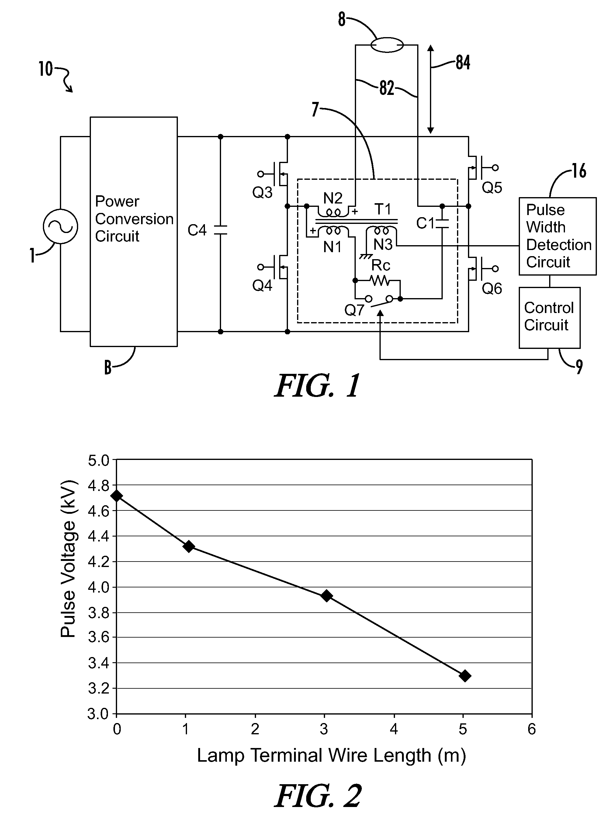
[0041]FIG. 1 is a circuit diagram in accordance with a first embodiment of the high-voltage discharge lamp lighting device 10. Power from a commercial AC power source 1 is converted into a predetermined DC voltage by a power conversion circuit B. The power conversion circuit B is formed of, for example, a full-wave rectifier for rectifying the AC power from the commercial AC power source 1, a step-up chopper circuit for stepping up the rectified output and a step-down chopper circuit for stepping down the output from the step-up chopper circuit. The output voltage of the power conversion circuit B is charged into a capacitor C4 and applied to a full bridge circuit formed of switching elements Q3, Q4, Q5, and Q6. The full bridge circuit is formed by parallel connection of a series circuit including switching elements Q3 and Q4 to a series circuit including switching elements Q5 and Q6, and converts a voltage of the capacitor C4 into a low-frequency rectangular wave voltage by alterna...


PUM


Abstract

A high-voltage discharge lamp lighting device provides a starting pulse voltage sufficient to turn on a high-voltage discharge lamp having terminal wire connections of variable length. A power conversion circuit is coupled to a commercial AC power source input and rectifies the AC input into a predetermined DC voltage output. A charging capacitor is coupled to the power conversion circuit. A full bridge circuit is coupled to the power conversion circuit and the charging capacitor and provides a rectangular wave AC output signal to a transformer primary winding circuit of at least a capacitor, a single switching element and a primary winding of a transformer. A low pulse voltage is induced in the primary winding and a transformer secondary winding is connected on one end to the high-voltage discharge lamp, wherein the low pulse voltage is stepped up to a high pulse voltage and applied to the high-voltage discharge lamp. A reference voltage is generated in a reference transformer winding representative of the high pulse voltage. A starting pulse equivalent value detection circuit is connected to the reference winding and detects a value associated with the reference voltage. A control circuit receives said value from said detection circuit, and variably controls at least one of a frequency of the single switching element or an ON impedance of the single switching element in association with said value, wherein said frequency or ON impedance is further associated with a starting pulse voltage sufficient to start the high-voltage discharge lamp.

Description

[0001]A portion of the disclosure of this patent document contains material that is subject to copyright protection. The copyright owner has no objection to the reproduction of the patent document or the patent disclosure, as it appears in the U.S. Patent and Trademark Office patent file or records, but otherwise reserves all copyright rights whatsoever.CROSS-REFERENCES TO RELATED APPLICATIONS[0002]This application claims benefit of the following patent application(s) which is / are hereby incorporated by reference: Japanese Patent Application No. JP2008-079043, filed Mar. 25, 2008STATEMENT REGARDING FEDERALLY SPONSORED RESEARCH OR DEVELOPMENT[0003]Not ApplicableREFERENCE TO SEQUENCE LISTING OR COMPUTER PROGRAM LISTING APPENDIX[0004]Not ApplicableBACKGROUND OF THE INVENTION[0005]The present invention relates to a high-voltage discharge lamp lighting device equipped with means adapted to adjust a peak value of a high-pressure pulse voltage at the time of start. The present invention fu...

Claims


Application Information

Patent Timeline
Patent Type & Authority Applications(United States)
IPC IPC(8): H05B41/36
CPCH05B41/042Y02B20/204H05B41/2881Y02B20/00
Inventor MATSUZAKI, NOBUTOSHIERIGUCHI, HIROYASUGORIKI, TAKESHIKAMOI, TAKESHIKOMATU, NAOKIKUMAGAI, JUNNAGATA, SATORUYAMAHARA, DAISUKEYUFUKU, AKIRA
Owner MATSUSHITA ELECTRIC WORKS LTD
Why Eureka
Try Eureka